Keyestudio Raspberry Pi Pico 42 in 1 Sensor Kit
1. Description
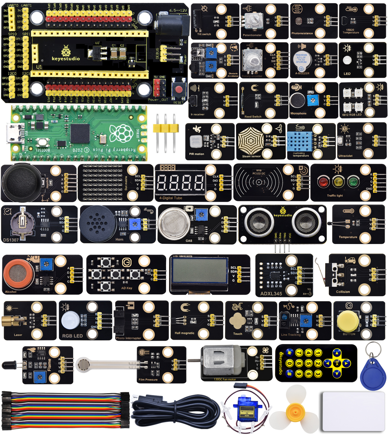
The Keyestudio Raspberry Pi Pico 42 in 1 sensor kit mainly contains 37 commonly used sensors/modules, a Raspberry Pi Pico board, a Raspberry Pi Pico expansion board and Dupont wires.
The 42 sensors and modules are fully compatible with the Raspberry Pi Pico shield. You only need to stack the Raspberry Pi Pico board onto the Raspberry Pi Pico shield, and hook up them with Dupont wires, which is simple and convenient.
To make you master the electronic knowledge, detailed tutorials (Micropython), schematic diagrams, wiring methods and test code are included. Through these projects, you will have a better understanding about programming, logic and electronics.
2. Kit
| # | Picture | Name | QTY |
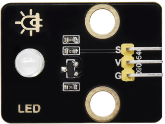 |
Keyestudio Purple LED Module | 1 | |
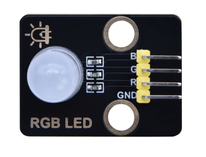 |
Keyestudio Common Cathode RGB Module | 1 | |
 |
Keyestudio Traffic Lights Module | 1 | |
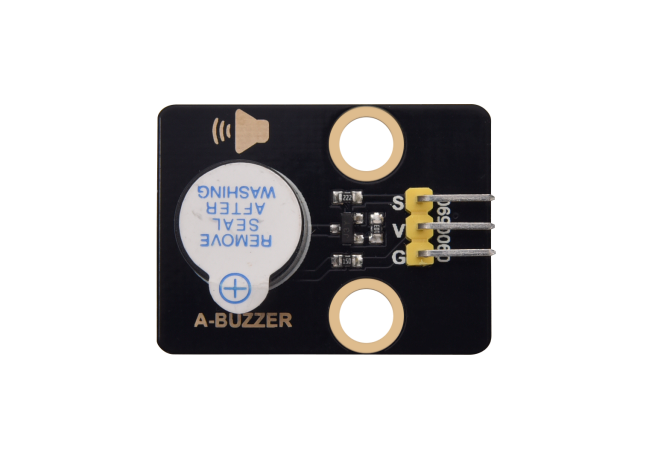 |
Keyestudio Active Buzzer | 1 | |
 |
Keyestudio 8002b Audio Power Amplifier | 1 | |
 |
Keyestudio Button Module | 1 | |
 |
Keyestudio Tilt Sensor | 1 | |
 |
Keyestudio PIR Motion Sensor | 1 | |
 |
Keyestudio Obstacle Avoidance Sensor | 1 | |
 |
Keyestudio 6812 RGB Module | 1 | |
 |
Keyestudio NTC-MF52AT Thermisto | 1 | |
 |
Keyestudio Photoresistor | 1 | |
 |
Keyestudio Sound Sensor | 1 | |
 |
Keyestudio Rotary Potentiometer |
1 | |
 |
Keyestudio IR Receiver | 1 | |
 |
Keyestudio Reed Switch Sensor | 1 | |
 |
Keyestudio Rotary Encoder Module | 1 | |
 |
Keyestudio Joystick Module | 1 | |
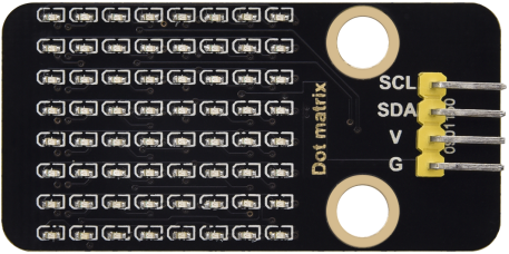 |
Keyestudio HT16K33 8X8 Dot Matrix Module | 1 | |
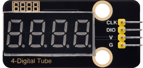 |
Keyestudio TM1650 4-Digit Tube Display | 1 | |
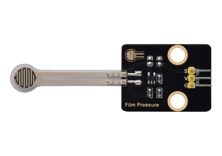 |
Keyestudio Thin-film Pressure Sensor | 1 | |
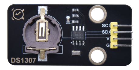 |
Keyestudio DS1307 Clock Sensor | 1 | |
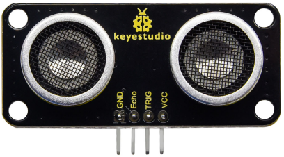 |
Keyestudio SR01 Ultrasonic Sensor | 1 | |
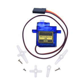 |
9G 90° Servo | 1 | |
 |
Keyestudio Capacitive Sensor | 1 | |
 |
Keyestudio Photo Interrupter | 1 | |
 |
Keyestudio Hall Sensor | 1 | |
 |
Keyestudio Flame Sensor | 1 | |
 |
Keyestudio line Tracking Sensor | 1 | |
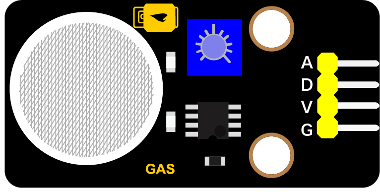 |
Keyestudio Analog Gas Sensor | 1 | |
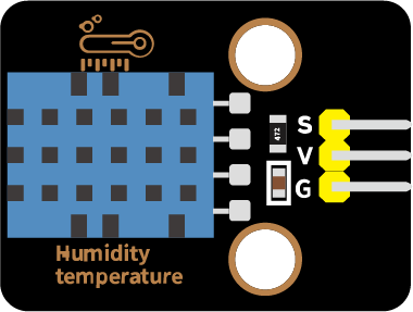 |
Keyestudio XHT11 Temperature and Humidity Sensor | 1 | |
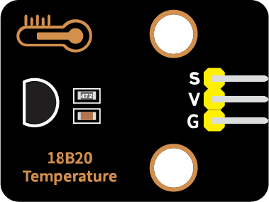 |
Keyestudio 18B20 Temperature Sensor | 1 | |
 |
keyestudio 130 Motor | 1 | |
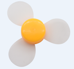 |
Fan | 1 | |
 |
Keyestudio Laser Module | 1 | |
 |
Keyestudio Steam Sensor | 1 | |
 |
Keyestudio Ultraviolet Sensor | 1 | |
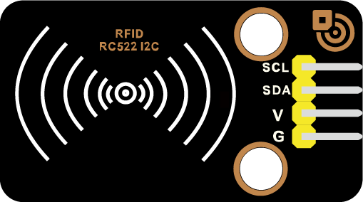 |
Keyestudio RFID Module | 1 | |
 |
Keyestudio Collision Sensor | 1 | |
 |
Keyestudio Alcohol Sensor | 1 | |
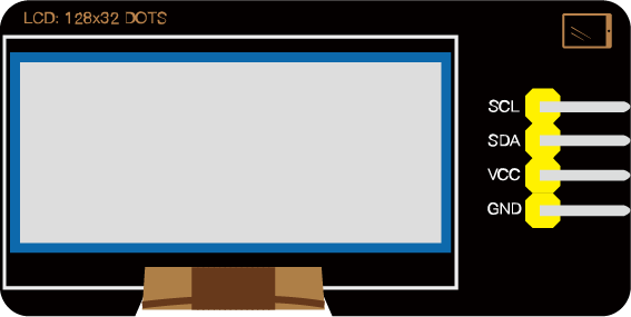 |
Kyestudio LCD_128X32_DOT Module | 1 | |
 |
5-Channel AD Button Module | 1 | |
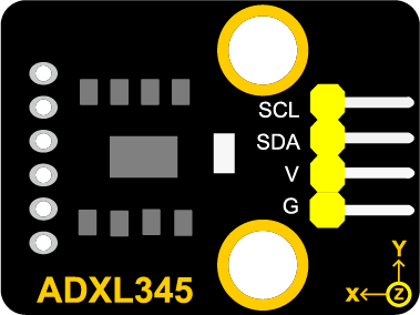 |
DXL345 Acceleration Module | 1 | |
 |
Raspberry Pi Pico Board | 1 | |
 |
Keyestudio Raspberry Pico IO Expansion Board | 1 | |
 |
Keyestudio JMFP-4 17-Key Remote Control(without batteries) | 1 | |
 |
USB Cable | 1 | |
 |
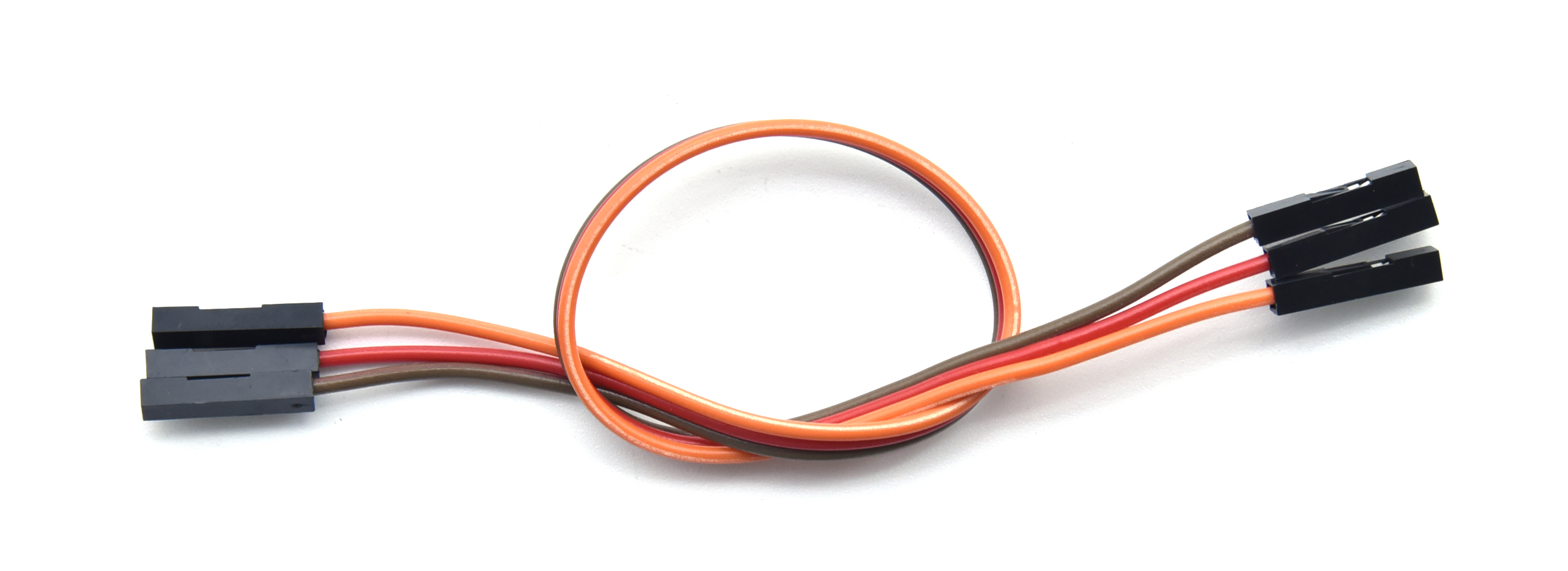
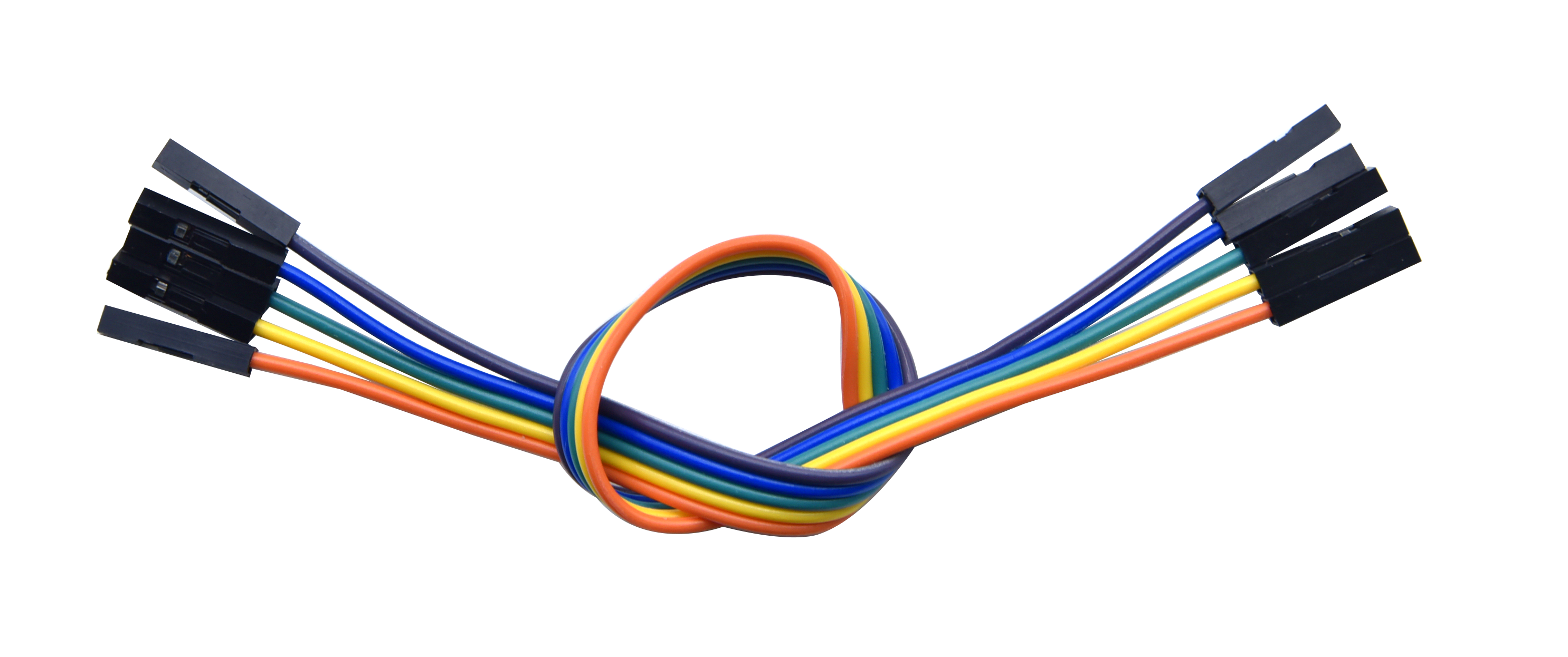
F-F Dupont Wire | 1 | |
 |
White Card | 1 | |
 |
ABS RFID Key | 1 |
3. Raspberry Pi Pico & Arduino IDE
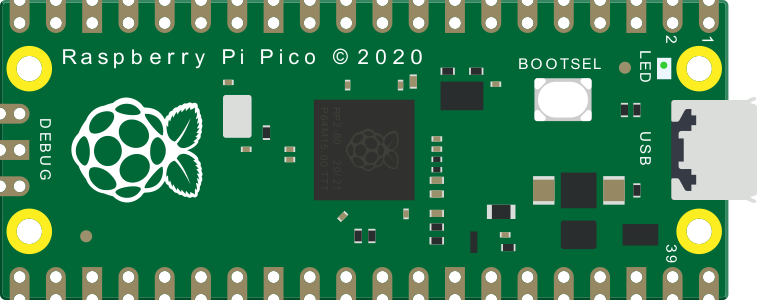
**3.1 Raspberry Pi Pico**

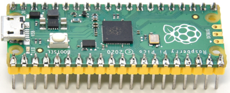
At the end of January 2021, the Raspberry Pi Foundation launched the Raspberry Pi Pico, which received a lot of attention due to its high-performance and low-cost.
The size of Pico is 21mm *51mm, which is similar to Arduino Nano
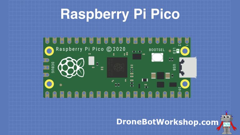
Raspberry Pi Pico is a low-cost, high-performance microcontroller board with flexible digital interfaces. It integrates the RP2040 microcontroller chip designed by Raspberry Pi, with dual-core Arm Cortex M0+ processor running up to 133 MHz, embedded 264KB of SRAM and 2MB of on-board Flash memory, as well as 26 multi-function GPIO pins. For software development, either Raspberry Pi’s C/C++ SDK, or the MicroPython is available. In this tutorial, we will use MicroPython.
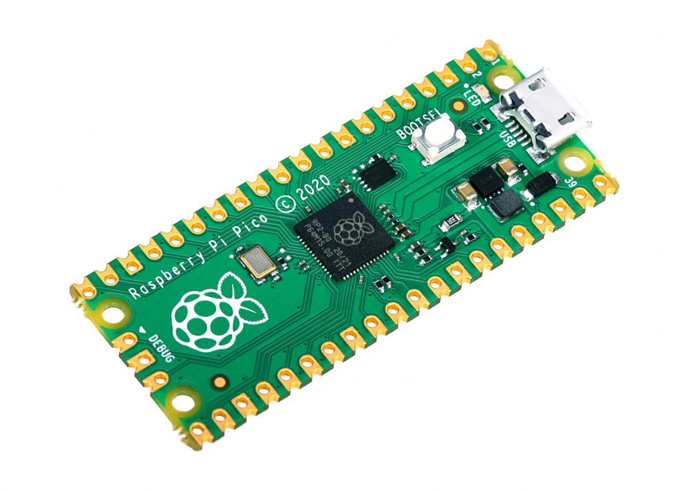
The bare board does not come with pins and you need to solder yourself. This is a well-made board that can also be used as an SMD component and soldered directly to a printed circuit board.
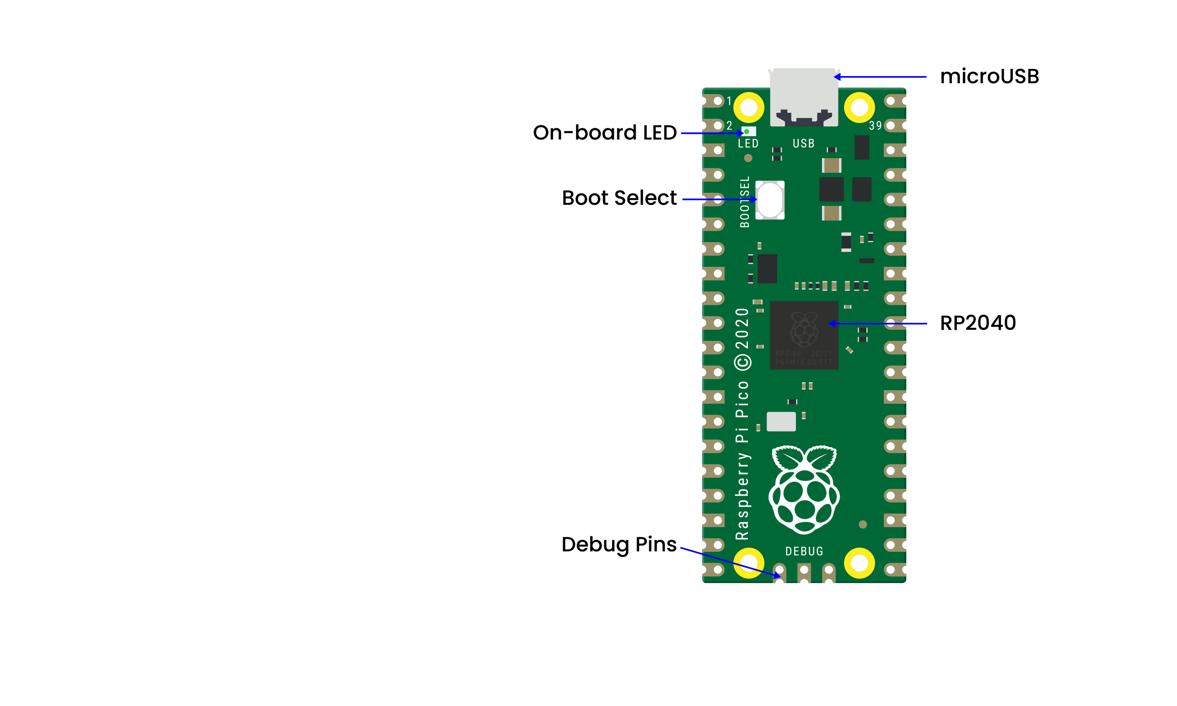
The most predominant feature on the board is the microUSB connector at one end. This is used both for communication and to supply power to the Pico. An on-board LED is mounted next to the microUSB connector, it is internally connected to GPIO pin 25. It’s worthwhile to note that this is the only LED on the entire Pico board.
The BOOTSEL pushbutton switch is mounted a bit down from the LED, it allows you to change the boot mode of the Pico so that you can load MicroPython onto it and perform drag-and-drop programming.
At the bottom of the board, you’ll see three connections, these are for a serial Debug option that we won’t be exploring here.
In the center of the board is the brains of the whole thing, the RP2040 MCU, which is capable of supporting up to 16MB of off-chip Flash memory, although in the Pico there is only 4MB.
Dual-core 32-bit Arm Cortex M0+ processor
Runs at 48MHz, but can be overclocked to 133MHz
30 GPIO pins
Can support USB Host or Device mode
8 Programmable I/O(PIO) state machines
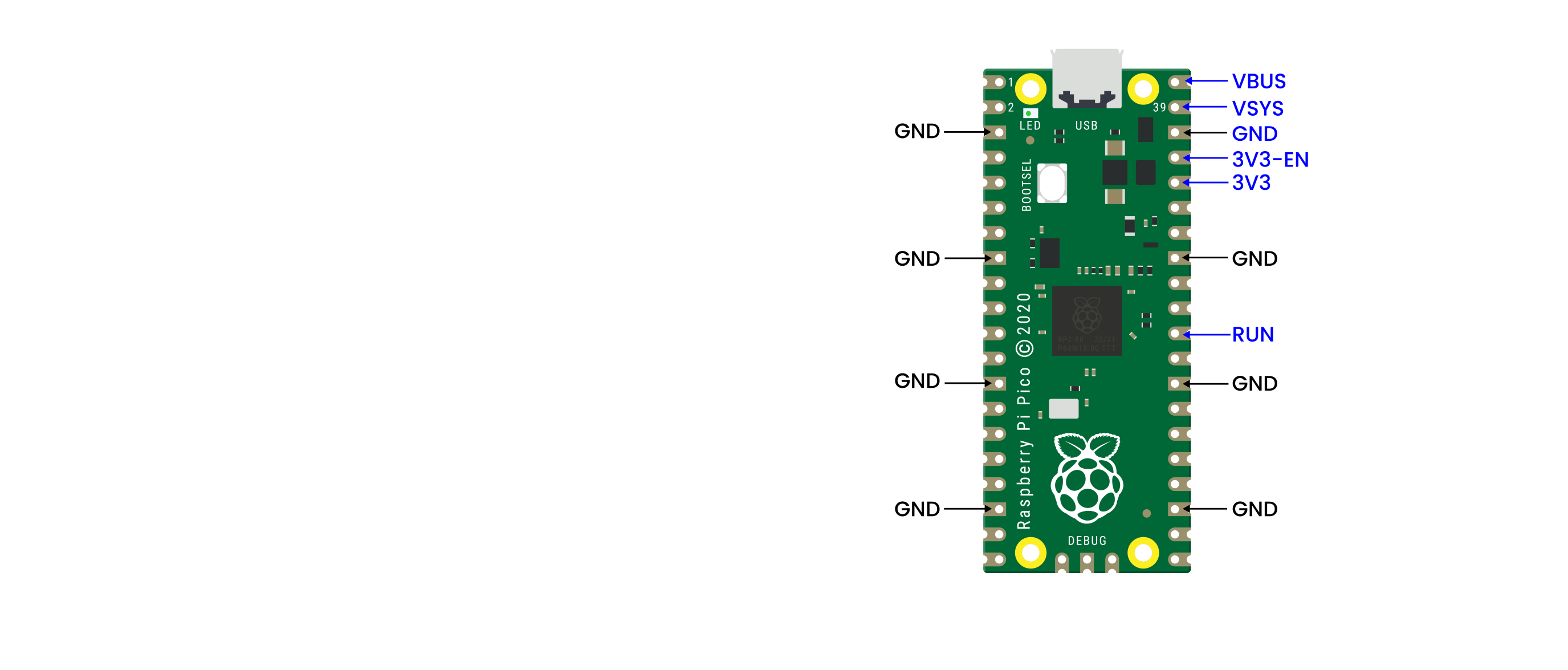
The Pico is a 3.3V logic device, however, it can be powered with a range of power supplies thanks to a built-in voltage converter and regulator.
GND: Ground connection. 8 grounding wires plus an additional one on the 3-pin Debug connector. They are square as opposed to rounded like the other connections.
VBUS: This is the power from the microUSB bus, 5 V. If the Pico is not being powered by the microUSB connector then there will be no output here.
VSYS: This is the input voltage, which can range from 2 to 5V. The on-board voltage converter will change it to 3.3V for the Pico.
3V3: This is a 3.3V output from the Pico’s internal regulator. It can be used to power additional components, providing you keep the load under 300ma.
3V3_EN: You can use this input to disable the Pico’s internal voltage regulator, which will shut off the Pico and any components powered by it.
RUN: It can enable or disable the RP2040 microcontroller, it can also reset it.
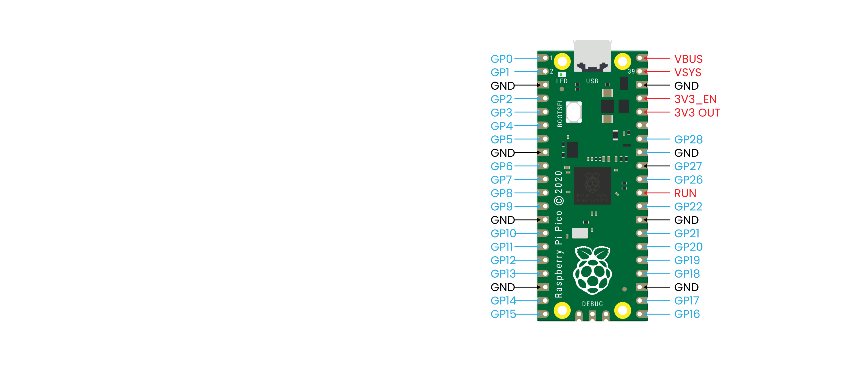
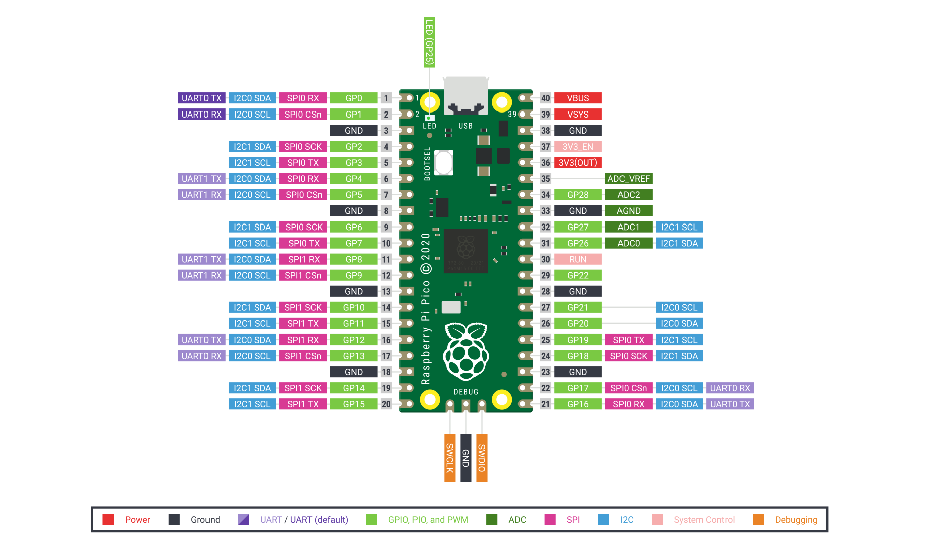
There are 26 exposed GPIO connections on the Raspberry Pi Pico board.They are laid out pretty-well in order, with a“gap”between GP22 and GP26 (those“missing”pins are used internally). All these pins have multiple functions, and you can configure up to 16 of them for PWM. There are two I2C buses, two UARTs, and two SPI buses, these can be configured to use a wide variety of GPIO pins.
The Pico has three Analog-to-Digital Converters, they are ADC0-GP26, ADC1-GP27, ADC2-GP28, and plus ADC-VREF converter used internally for an on-board temperature sensor. Note: The ADCs have a 12-bit resolution. However, the Micropython has scaled the 12-bit resolution into a 16-bit resolution, which means that we will receive ADC values from 0 to 65535. The microcontroller’s working voltage is 3.3V, indicating that 0 corresponds to 0V and 65535 corresponds to 3.3V.
You can also provide an external precision voltage-reference on the ADC_VREF pin. One of the grounds, the ADC_GND on pin 33 is used as a ground point for that reference.
| Raspberry Pi Pico Configuration |
| Dual-core Arm Cortex-M0 + @ 133MHz |
| 2 × SPI, 2 × I2C, 2 × UART |
| 264KB of SRAM, and 2MB of on-board Flash memory |
| 16 PWM channels |
| QSPI bus controller, supporting up to 16 MB of external Flash memory |
| USB 1.1 with host and device support |
| DMA controller |
| 8 × Programmable I/O (PIO) state machines for custom peripheral support |
| 30 GPIO pins, 4 of which can optionally be used as analog inputs |
| Drag-and-drop programming using mass storage over USB |
Pin out
Raspberry Pi did release a ton of technical documentation, plus a great guide called Get Started with MicroPython on Raspberry Pi Pico. It’s available in softcover, and as a PDF download as well. For more information, please refer to:
https://www.raspberrypi.com/products/raspberry-pi-pico/
4. Install Arduino IDE and Driver
Installing Arduino IDE
When you get control board, you need to download Arduino IDE and driver firstly.
You could download Arduino IDE from the official website:
https://www.arduino.cc/, click the SOFTWARE on the browse bar, click“DOWNLOADS”to enter download page, as shown below:

There are two versions of IDE for WINDOWS system. You can choose between the installer (.exe) and the Zip file. For installer, it can be directly downloaded, without the need of installing it manually. However, for Zip package, you will need to install the driver manually.
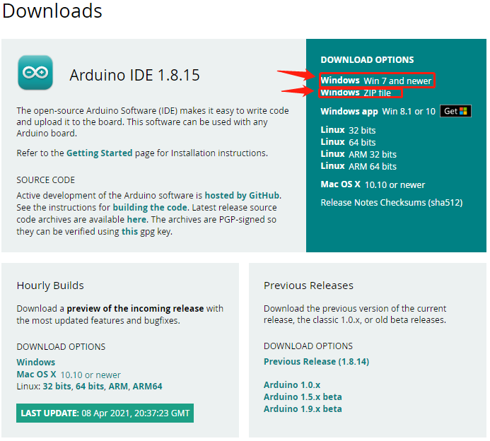

Click JUST DOWNLOAD.
Setting Arduino IDE
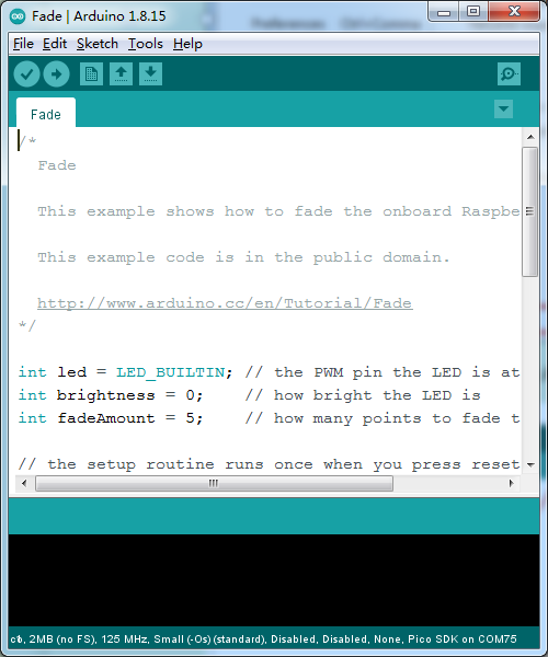
Click icon,and open Arduino IDE.
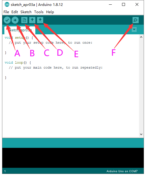
A- Used to verify whether there is any compiling mistakes or not.
B- Used to upload the sketch to your Arduino board.
C- Used to create shortcut window of a new sketch.
D- Used to directly open an example sketch.
E- Used to save the sketch.
F- Used to send the serial data received from board to the serial monitor.
Set pico environment: (https://github.com/earlephilhower/arduino-pico)
Select(File) → (Preferences)
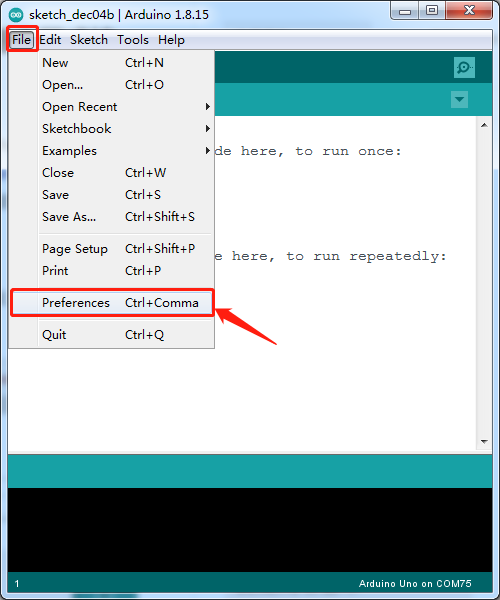
Copy the following URL in the Additional Boards Manager URLs page
https://github.com/earlephilhower/arduino-pico/releases/download/global/package_rp2040_index.json
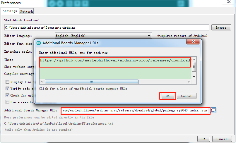
Click OK and return the mange page.
Select (Tools)→ (Board) → (Board Manager)
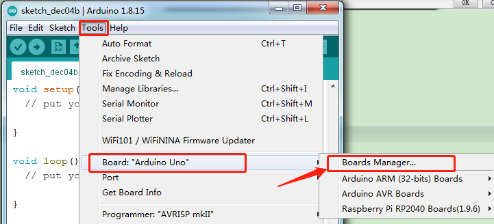
Enter pico in the searching bar, as shown below.
Then click Install.
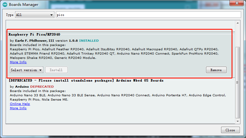
The IDE is installed.
Then return the main page to select (Tools)→(Board) → Raspberry Pi RP2040 Boards(1.9.6) → Raspberry Pi Pico
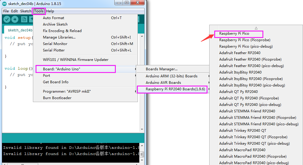
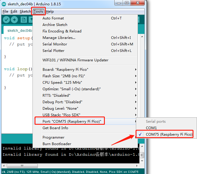
Select the development board and the port connected to Pico.
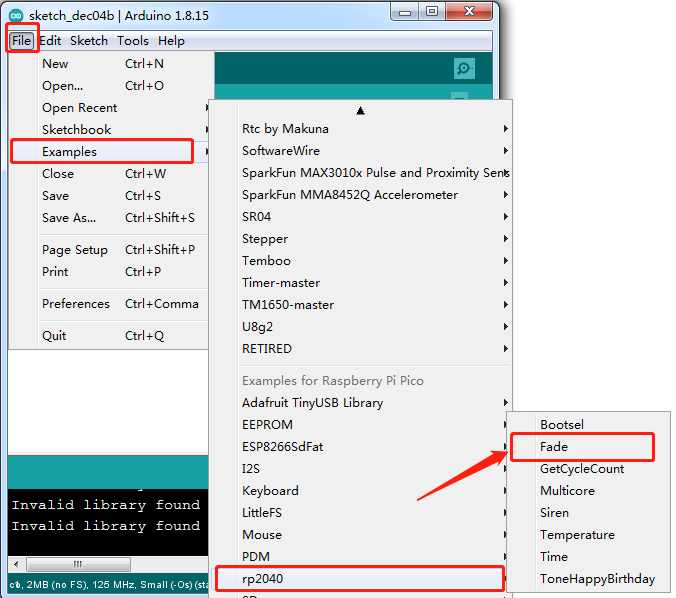
We can make on-board LED show changes of light brightness:
Select(File)→ (Examples)→ rp2040→ Fade.
How to upload the test code
Power off the Pi Pico board
Press and hold the white BOOTSEL button on the development board, then interface a power supply via a USB cable.
Click
 to upload and compile.
Wait until the “Compiling sketch…” is compiled, and the following prompt message appears “Uploading…”, then release the BOOTSEL button
Release the BOOTSEL button if the information box shows“Uploading…”. The code won’t be uploaded successfully until“Done uploading.”appears
After uploading the test code, select the corresponding port and click upload directly. Then you can see that the LED on the development board become from dark to bright, then from bright to dark, like human breathe.
Add Libraries
Right-click Arduino and enter libraries folder of Arduino
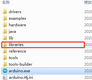
Then copy libraries you need in the libraries of Arduino.
Keyestudio Raspberry Pico IO Shield
Description
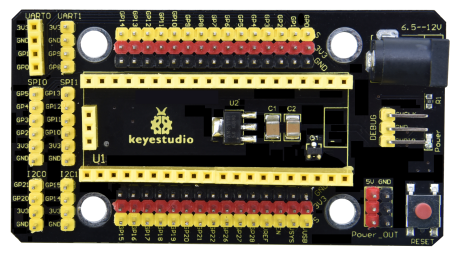
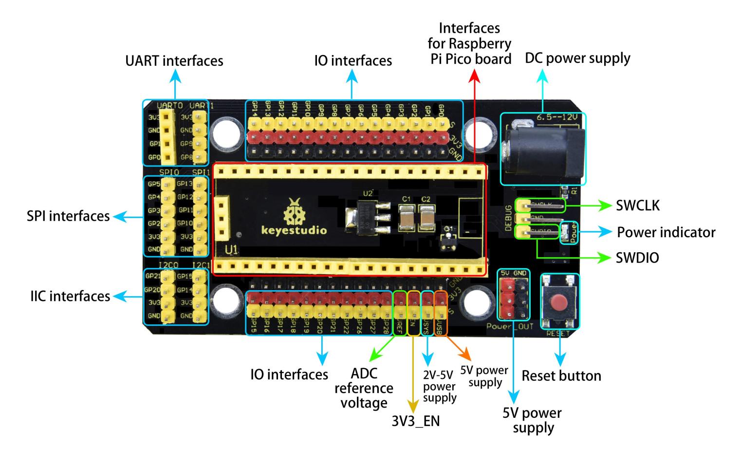
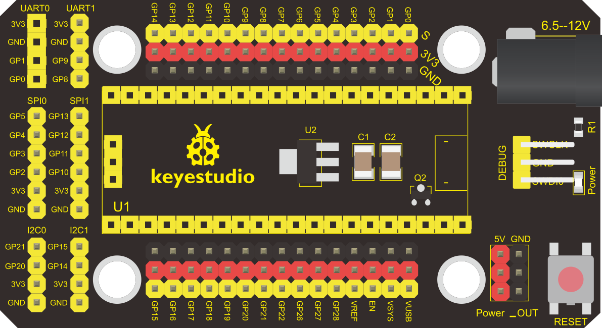
The Keyestudio Raspberry Pico IO shield is designed for Raspberry Pi Pico. No soldering is required. To make the connection easier, interfaces on the shield have silkscreen.
On the shield, G, V and S represent GND, the VCC interface (3.3V) and digital ports or analog ports.
The shield comes with pin headers with 2.54mm spacing, a reset button, a PWR power indicator and four LEGO position holes.
Additionally, it boasts a variety of communication interfaces as I2C, UART, SPI, analog IO and digital IO, and a power supply port(6.5-12V).
Specification:
Output current: ≦500mA
DC input voltage: 6.5 - 12V
Output voltage: DC 3.3V/5V
Ambient temperature(recommended): -10°C ~ 50°C
Dimensions: 45.339MM *83.617MM
Pin pitch: 2.54mm
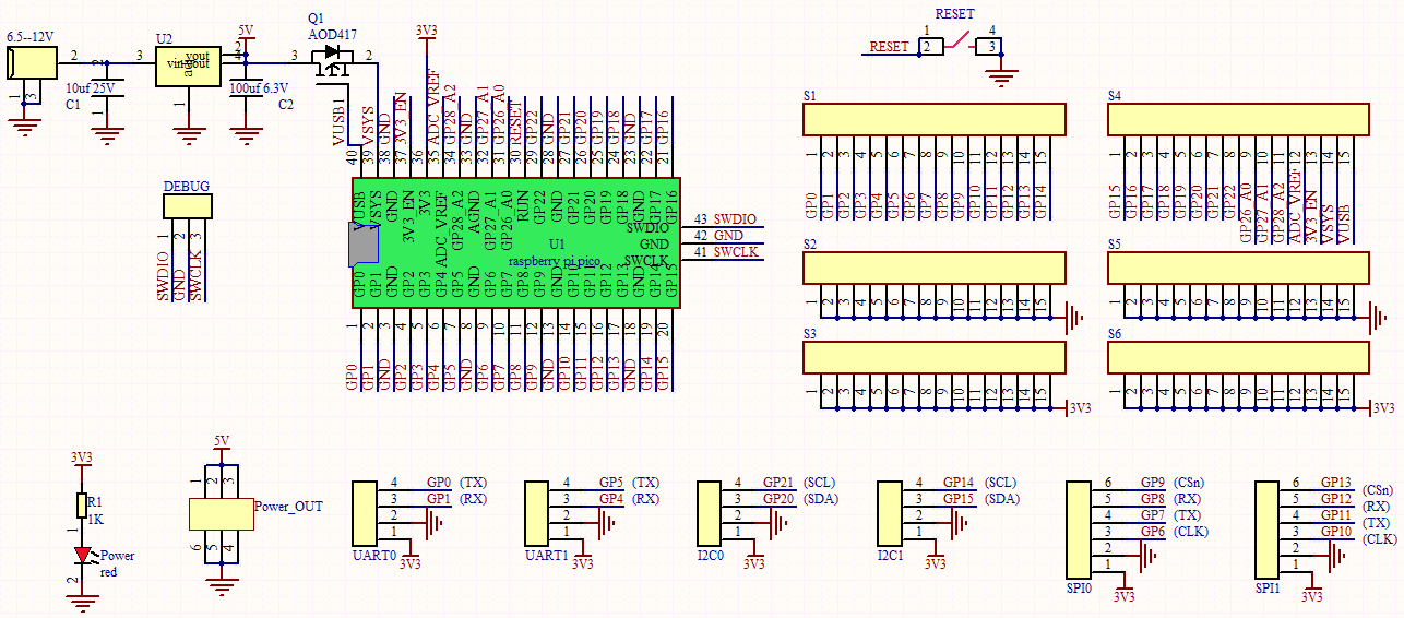
Schematic Diagram
Pinout
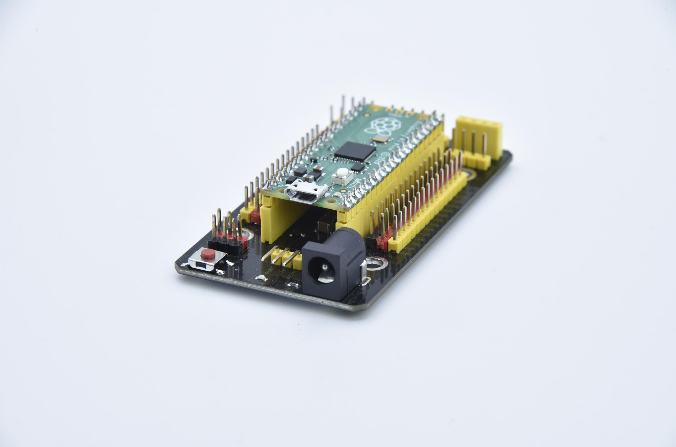
As shown below, stack the Raspberry Pi Pico board onto the Raspberry Pi Pico shield.
5. Projects
There are 42 sensors and modules in this kit. Next, we will analyze and introduce how they work step by step. Interface sensors with the Raspberry Pi Pico board and the Pico shield, run test codes and observe experimental phenomenon.
Note: please wire up components according to the given connection diagrams.
Project 1: Lighting up LED

Overview
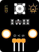
In this project, we will make an experiment to light up the white LED module. The high and low levels can be controlled by programming, then the state of the LED can be controlled.
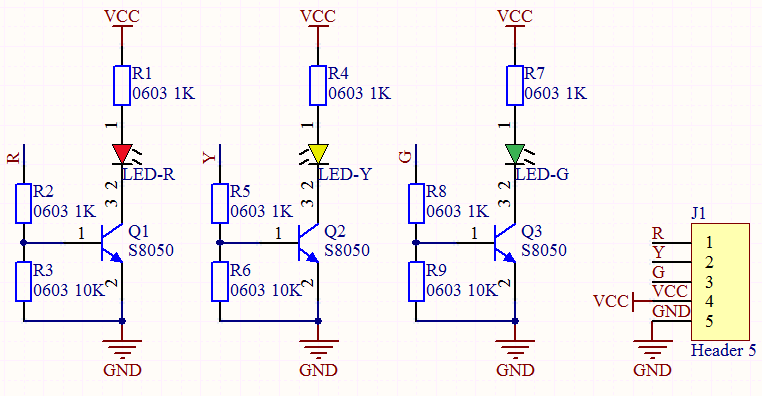
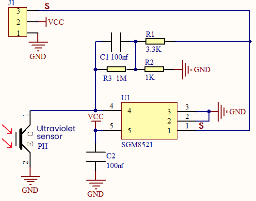
Working Principle
The two circuit diagrams are given. The left one is wrong wiring-up diagram. Why? Theoretically, when the S terminal outputs high levels, LED will receive the voltage and light up.
Due to limitation of IO ports of Pico board, weak current can’t make LED brighten.
The right one is correct wiring-up diagram. GND and VCC are powered up. When the S terminal is a high level, the triode Q1 will be connected and LED will light up(note: current passes through LED and R3 to reach GND by VCC not IO ports). Conversely, when the S terminal is a low level, the triode Q1 will be disconnected and LED will go off.
The triode Q1 is equal to a switch and R1 and R3 stand for limited resistors which can curb the size of current to prevent from burning out components


Components
 |
 |
 |
 |
|
| Raspberry Pi Pico Board*1 | Raspberry Pi Pico Expansion Board*1 | Keyestudio Purple LED Module*1 | 3P Dupont Wire*1 | Micro USB Cable*1 |
Wiring Diagram
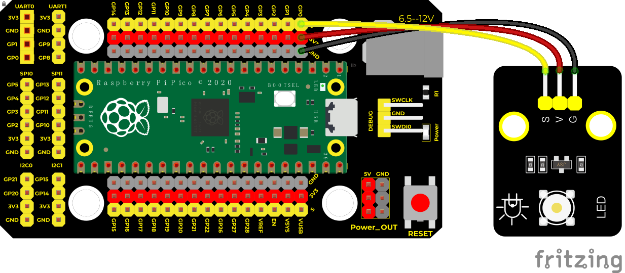
Test Code
Code 1:
/*
* Keyestudio 42 in 1 Starter Kit for Raspberry Pi Pico
* lesson 1.1
* LED
* http://www.keyestudio.com
*/
**void setup() **
**void loop() **
Code 2:
/*
* Keyestudio 42 in 1 Starter Kit for Raspberry Pi Pico
* lesson 1.2
* Blink
* http://www.keyestudio.com
*/
int ledPin = 0; //define LED pin as GP0
**void setup() **
**void loop() **
Code Explanation
Machine module is indispensable, we will use import machine or from machine import… to program pico with microPython.
time.sleep() function is used to set delayed time, as time.sleep(0.01), which means, the delayed time is 10ms.
led = Pin(0, Pin.OUT),created a pin example and we name led.
0 is indicative of connected pin GP0,Pin.OUT represents output mode, can use .value() to output high levels (3.3V)led.value(1) or low levels (0V)led.value(0)。
import machine is used to import modules. When creating pins examples, it will change into led = machine.Pin(0, machine.Pin.OUT)
2. while True is loop function,
It means that sentences under this function will loop unless True changes into False. For the function while,led.value(1), outputs high levels to the pin 0; then LED lights up. Then the delayed function time.sleep(1) will wait for 1s. When led.value(0) output low levels to the pin 0, the LED will go off,and the function time.sleep(1) will wait for 1s, cyclically, and LED will flash.
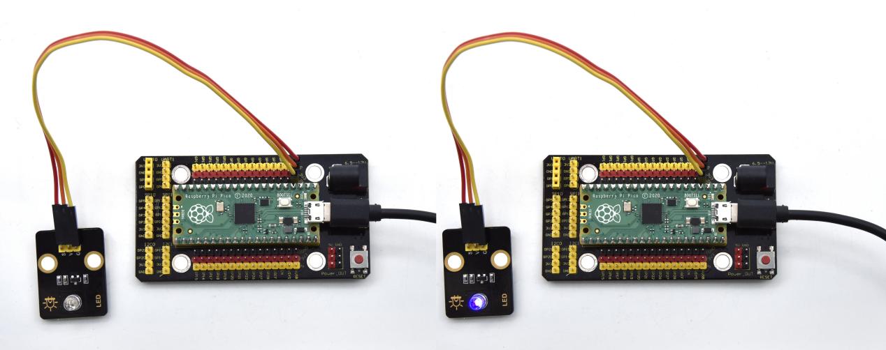
Test Result
Code 1: upload the code and power on, the purple LED on the module will light up
Code 2: upload the code and power on, the purple LED will flash with the interval of 1s.
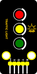
Project 2: Traffic Light Module

Overview
In this lesson, we will learn how to control multiple LED lights and simulate the operation of traffic lights.
Traffic lights are signal devices positioned at road intersections, pedestrian crossings, and other locations to control flows of traffic.
In this kit, we will use the traffic light module to simulate the traffic light.
Working Principle
In previous lesson, we already know how to control an LED. In this part, we only need to control three separated LEDs. Output high levels to the signal R(3.3V), then the red LED will be on.
Components
|
|
 |
 |
|
| Raspberry Pi Pico Board*1 | Raspberry Pi Pico Shield*1 | Keyestudio DIY Traffic Lights Module*1 | 5P Dupont Wire *1 | Micro USB Cable*1 |
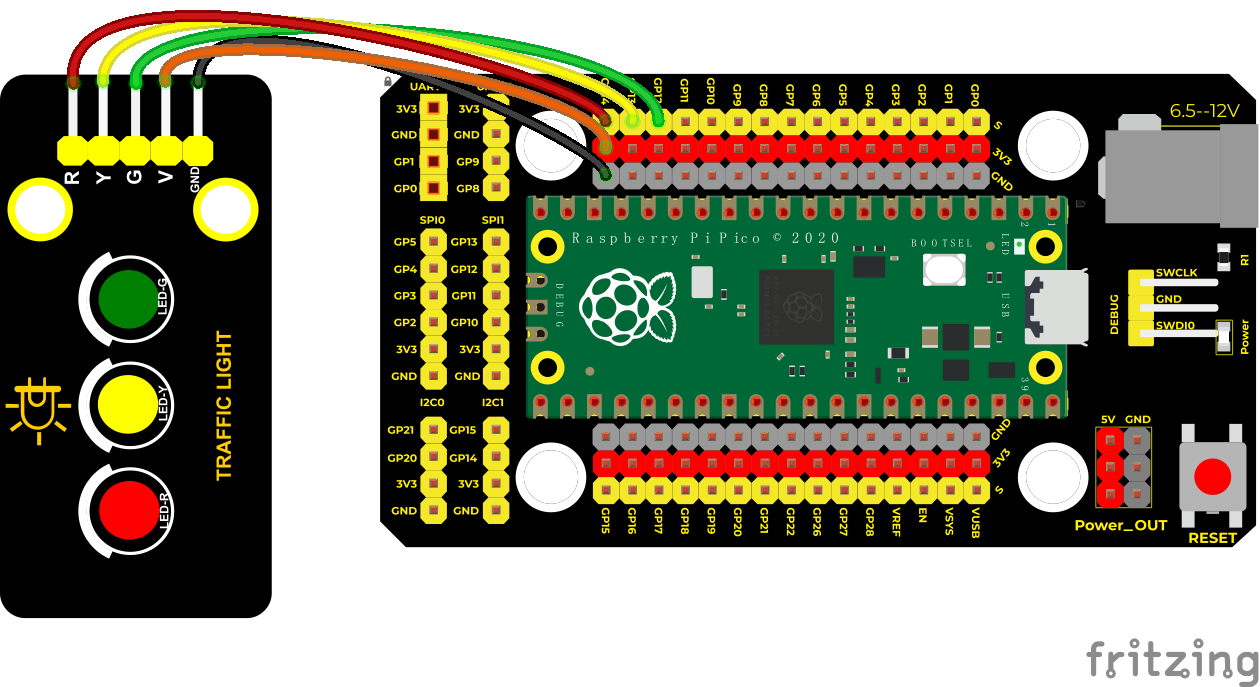
Wiring Diagram
Test Code
/*
* Keyestudio 42 in 1 Starter Kit for Raspberry Pi Pico
* lesson 2
* Traffic_Light
* http://www.keyestudio.com
*/
int greenPin = 12; //the green LED is connected to GP12
int yellowPin = 13; //the yellow LED is connected to GP13
int redPin = 14; //the red LED is linked with GP14
**void setup() **
**void loop() **
digitalWrite(redPin, HIGH); //light up the LED
delay(5000); //delay in 5s
digitalWrite(redPin, LOW); //turn off the red LED
}
Code Explanation
We use the function for(). for (int i = 1; i <= 3; i = i + 1) represents the variable i adds 1 fir each time from 1 to 3.
The function for (int i = 255; i >= 0; i = i - 1) indicates that i reduces by 1 each time. When i<0, exit the for() loop and execute 256 times
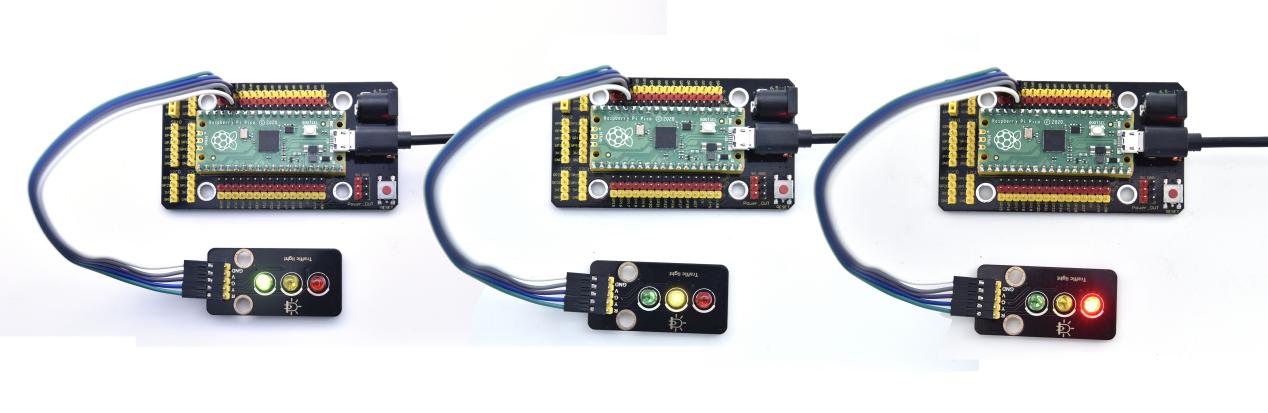
Test Result
Upload the code, the green LED will be on for 5s then off, the yellow LED will flash for 3s then go off and the red one will be on 5s then off.
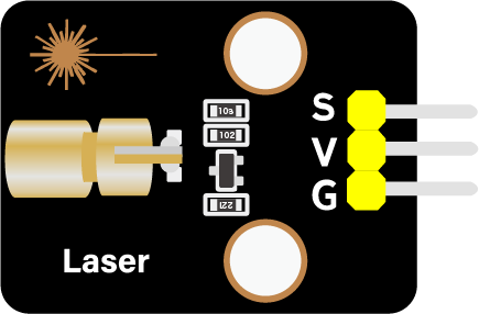
Project 3: Laser Sensor

Description
Lasers are widely used to cut, weld, surface treat, and more on specific materials. The energy of the laser is very high. The toy laser pointer may cause glare to the human eye, and it may cause retinal damage for a long time. my country also prohibits the use of laser to illuminate the aircraft.
Working Principle
The laser head sensor module is mainly composed of a laser head with a light-emitting die, a condenser lens, and a copper adjustable sleeve.
We can see the circuit schematic diagram of this module which is very similar to the LED we have learned. They are all driven by triodes. A high-level digital signal is directly input at the signal end, then the sensor will start to work; if inputting low levels, the sensor won’t work
|
|
|
|
|
| Raspberry Pi Pico Board*1 | Raspberry Pi Pico Expansion Board*1 | Keyestudio White LED Module*1 | 3P Dupont Wire*1 | Micro USB Cable*1 |
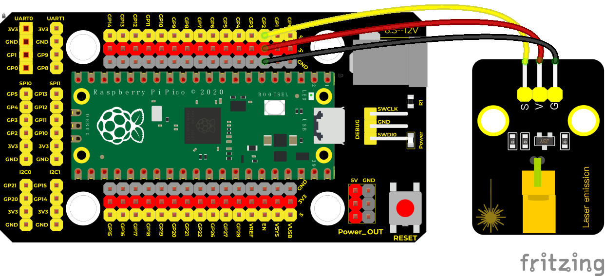
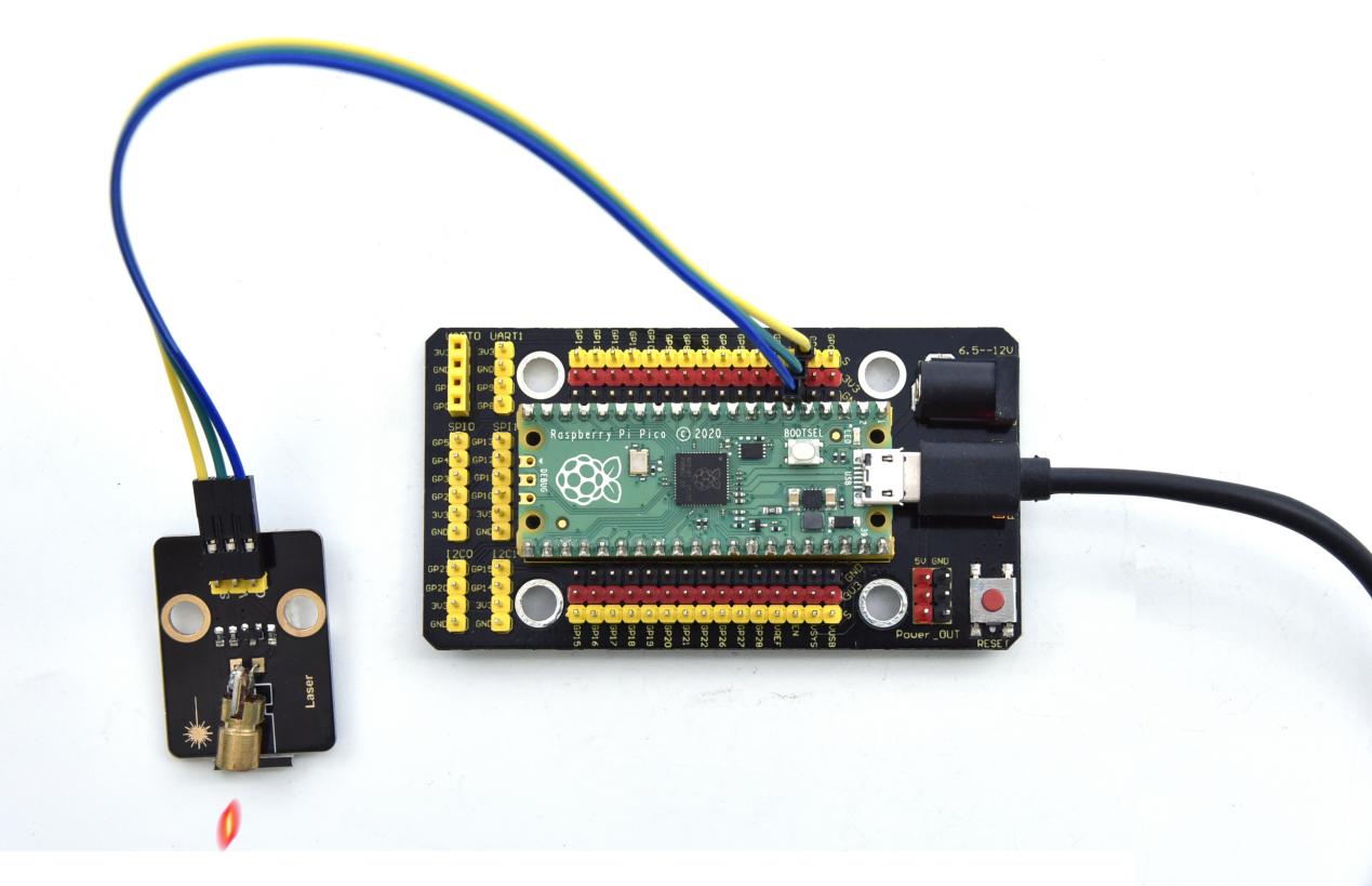
Wiring Diagram
Test Code
/*
* Keyestudio 42 in 1 Starter Kit for Raspberry Pi Pico
* lesson 3
* Laser sensor
* http://www.keyestudio.com
*/
int laserPin = 2; //define the laser pin as 2
**void setup() **
**void loop() **
Test Results
Upload the test code successfully and power on, the laser module will emit red laser signals for 2 seconds and stop emitting signals for 2 seconds.
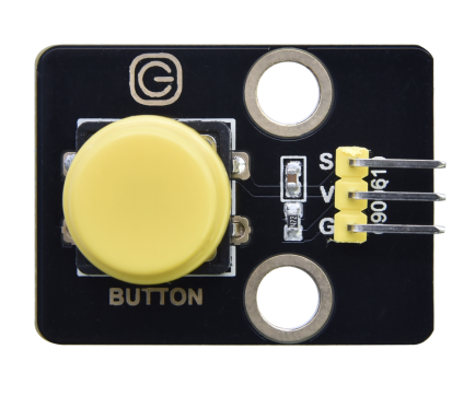
Project 4: Button Sensor

Overview
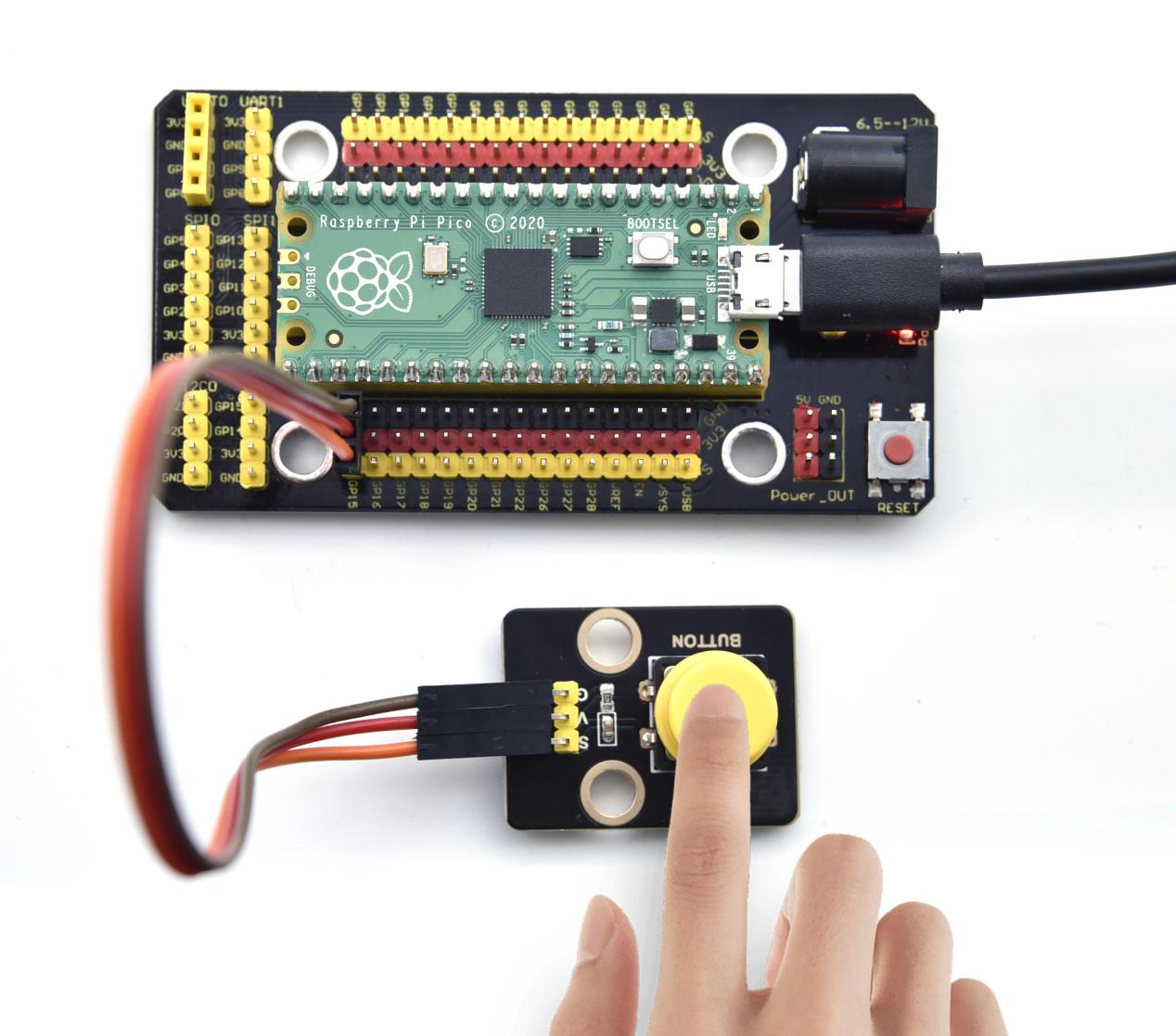
In this kit, there is a Keyestudio single-channel button module, which mainly uses a tact switch and comes with a yellow button cap.
In previous lessons, we learned how to make the pins of our single-chip microcomputer output a high level or low level. In this experiment, we will read the high level (3.3V) and low level (0V).
We can determine whether the button on the sensor is pressed by reading the high and low level of the S terminal on the sensor.
Working Principle
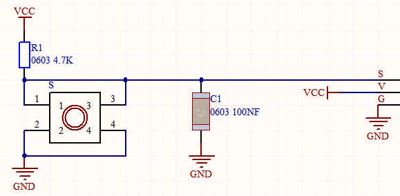
The button module has four pins. The pin 1 is connected to the pin 3 and the pin 2 is linked with the pin 4. When the button is not pressed, they are disconnected. Yet, when the button is pressed, they are connected. If the button is released, the signal end is high level.
Components
|
|
 |
|
|
| Raspberry Pi Pico Board*1 | Raspberry Pi Pico Shield*1 | Keyestudio Button Sensor*1 | 3P Dupont Wire*1 | Micro USB Cable*1 |
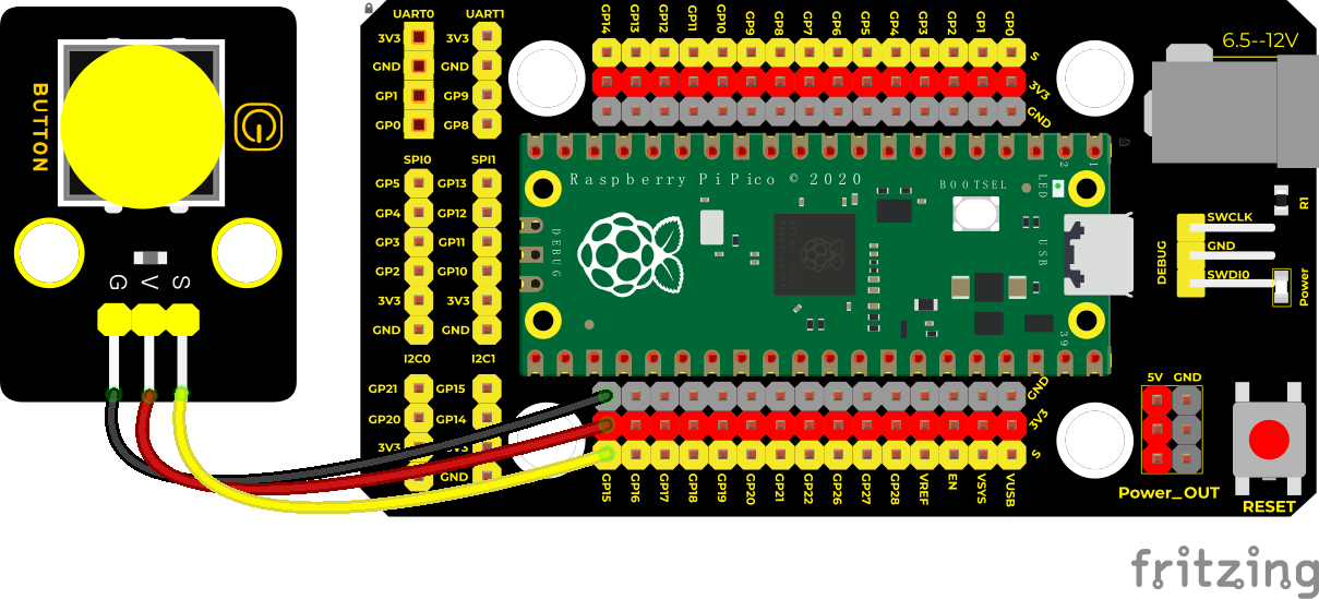
Wiring Diagram
Test Code
/*
* Keyestudio 42 in 1 Starter Kit for Raspberry Pi Pico
* lesson 4
* button
* http://www.keyestudio.com
*/
int val = 0; //used to save values of buttons
int button = 15; //the pin of the button is connected to GP15
**void setup() **
**void loop() **
**else **
}
Code Explanation
1. pinMode(button, INPUT); set the pin of the button module to GP15 and INPUT.
Configure INPUT through pinMode(). INPUT must use the pull-up or pull-down resistor(ours module has the pull-up resistor RI).
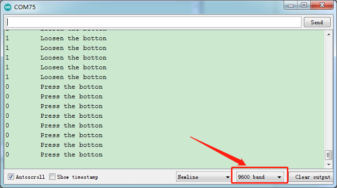
2. Serial.begin(9600): Initialize serial communication and set the baud rate to 9600.
3. digitalRead(button): read the digital level of the button(HIGH or LOW). If this pin is not connected to pins, the digitalRead() will return HIGH or LOW.
4. if..else..:if the logic behind () is true, execute the code of (); otherwise execute the code of else.
5. If the button is pressed, the signal end is low level, GP15 is low level and Val is 0. Then the monitor will show the corresponding value and characters; otherwise, the sensor is released, val is 1 and monitor will show 1 and other characters
Test Result
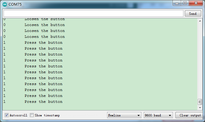
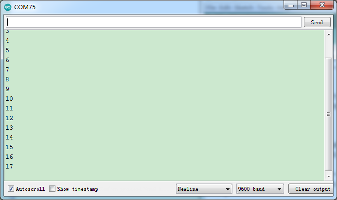
Upload the test code successfully. After powering on the USB cable, open the serial monitor and set the baud rate to 9600. The serial monitor will display the corresponding data and characters. When the button is pressed, val is 0, the monitor will show“Press the button”;when the button is released, val is 1,the monitor will show“Loosen the button”; as shown below
Project 5: Capacitive Sensor

Description
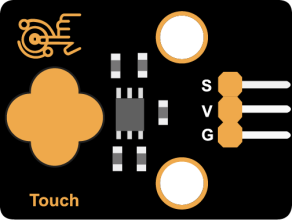
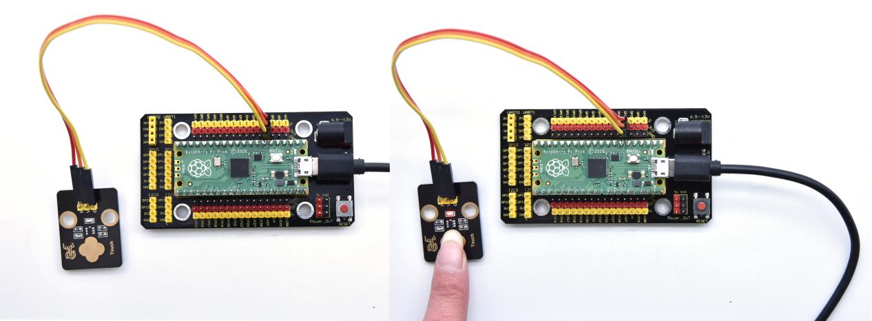
In this kit, there is a capacitive touch module which mainly uses a TTP223-BA6 chip. It is a touch detection chip, which provides a touch button, and its function is to replace the traditional button with a variable area button. When we power on, the sensor needs about 0.5 seconds to stabilize. Do not touch the keys during this time period. At this time, all functions are disabled, and self-calibration is always performed. The calibration period is about 4 seconds. We display the test results in the shell.
Working Principle

When our fingers touch the module, the signal S outputs high levels, the red LED on the module flashes. We can determine if the button is pressed or not by reading high and low levels on the sensor.
Required Components
|
|
 |
|
|
| Raspberry Pi Pico Board*1 | Raspberry Pi Pico Expansion Board*1 | Keyestudio DIY Capacitive Module*1 | 3P Dupont Wire*1 | Micro USB Cable*1 |
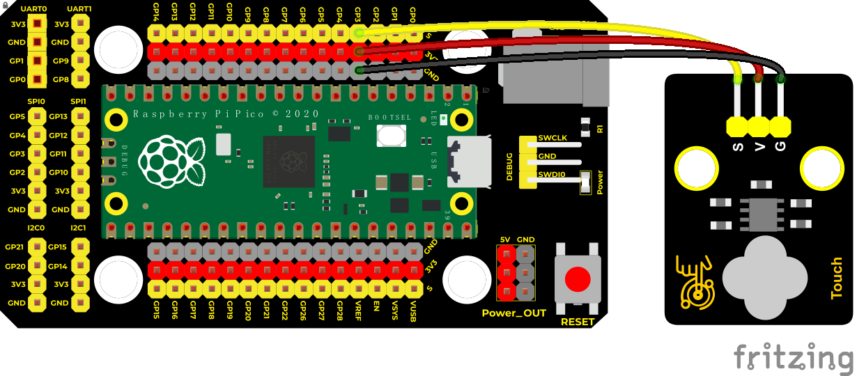
Wiring Diagram
Test Code
/*
* Keyestudio 42 in 1 Starter Kit for Raspberry Pi Pico
* lesson 5
* Touch sensor
* http://www.keyestudio.com
*/
int val = 0;
int button = 3; //Pins of the button sensor
**void setup() **
**void loop() **
**else **
}
Code Explanation
When we touch the sensor, the monitor will show“You pressed the button!”, if not,“You loosen the button!”will be shown on the monitor.
Test Result
The monitor shows corresponding data and characters. In the experiment, when the button is pressed, the red LED lights up and val is 1. Then the shell shows “You pressed the button!”; if the button is released, the red LED is off and val is 0,“You loosen the button!”will be displayed
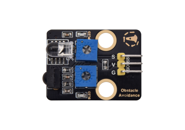
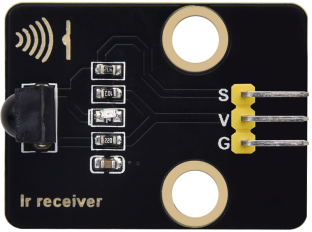
Project 6: Obstacle Avoidance Sensor

Overview
In this kit, there is a Keyestudio obstacle avoidance sensor, which mainly uses an infrared emitting and a receiving tube. In the experiment, we will determine whether there is an obstacle by reading the high and low level of the S terminal on the sensor.
Working Principle
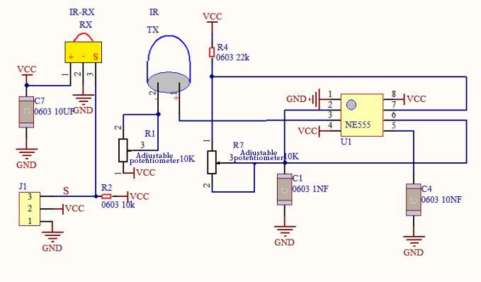
NE555 circuit provides IR signals with frequency to the emitter TX, then the IR signals will fade with the increase of transmission distance. If encountering the obstacle, it will be reflected back.
When the receiver RX meets the weak signals reflected back, the receiving pin will output high levels, which indicates the obstacle is far away. On the contrary, it the reflected signals are stronger, low levels will be output, which represents the obstacle is close. There are two potentiometers on the module, and one is for adjusting emission power, another one is for receiving frequency.
Components
|
|
 |
|
|
| Raspberry Pi Pico Board*1 | Raspberry Pi Pico Expansion Board*1 | Keyestudio DIY Obstacle Avoidance Sensor*1 | 3P Dupont Wire*1 | Micro USB Cable*1 |
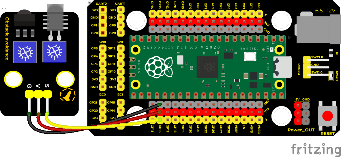
Wiring Diagram
Test Code
/*
* Keyestudio 42 in 1 Starter Kit for Raspberry Pi Pico
* lesson 6
* obstacle avoidance sensor
* http://www.keyestudio.com
*/
int val = 0;
**void setup() **
**void loop() **
**else **
}
Note:
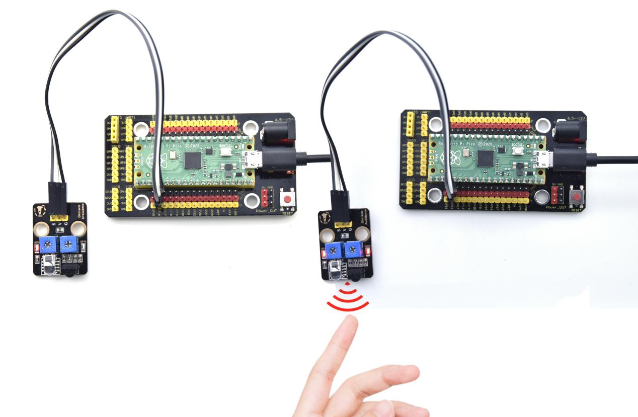
Upload the test code and wire up according to the connection diagram. After powering on, we start to adjust the two potentiometers to sense distance.
Adjust the potentiometer transmitting power. Make the P LED at the critical point of ON and OFF states.
2. Adjust the potentiometer receiving frequency. Rotate it clockwise, the frequency will increase. Make the S LED at the critical point of ON and OFF states, then the 38KHz square wave can be produced.
Test Result
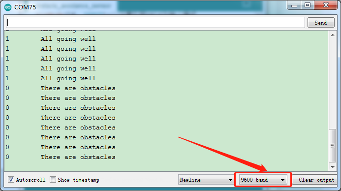
Upload the code power up by a USB cable, open the serial monitor and set baud rate to 9600. When the sensor detects the obstacle, the monitor will show“There are obstacles”; if the obstacle is not detected, “All going well” will be shown.
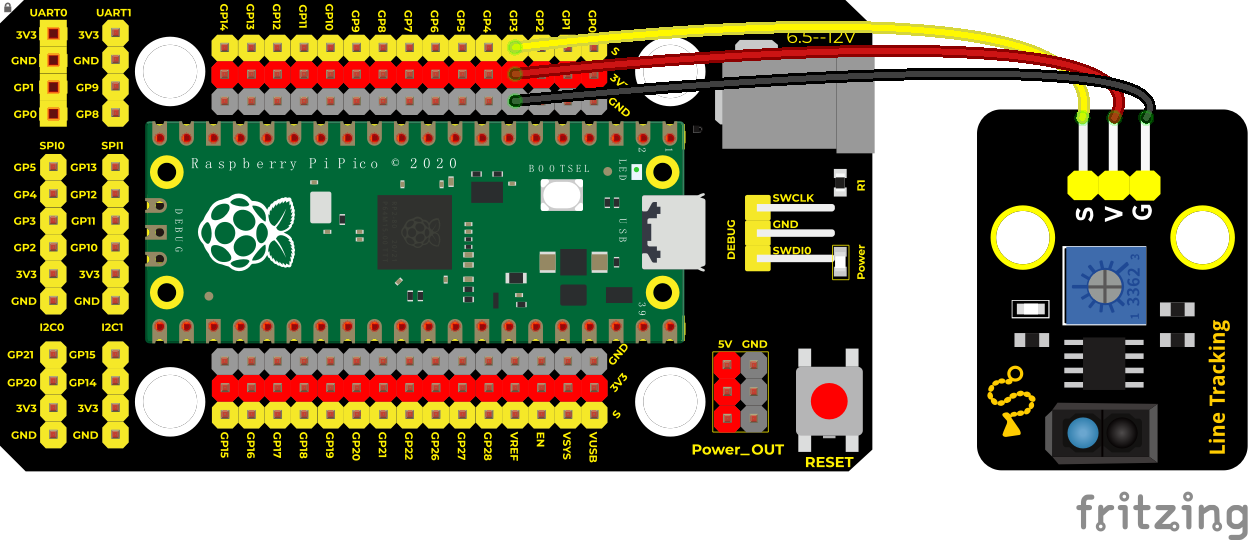
Project 7: Line Tracking Sensor
Description
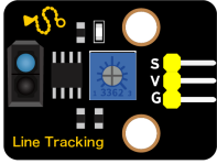
In this kit, there is a DIY electronic building block single-channel line tracking sensor which mainly uses a TCRT5000 reflective black and white line recognition sensor element.
In the experiment, we judge the color (black and white) of the object detected by the sensor by reading the high and low levels of the S terminal on the module; and display the test results on the shell.
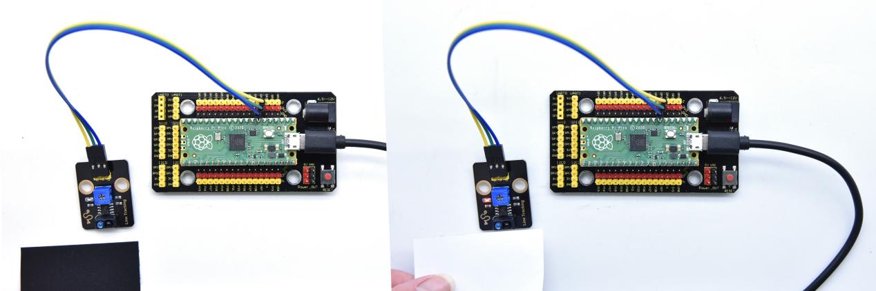
Working Principle
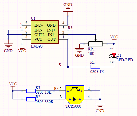
When a black or no object is detected, the signal terminal will output high levels; when white object is detected, the signal terminal is low level; its detection height is 0-3cm. We can adjust the sensitivity by rotating the potentiometer on the sensor. When the potentiometer is rotated, the sensitivity is best when the red LED on the sensor is at the critical point between off and on.
Required Components
|
|
 |
|
|
| Raspberry Pi Pico Board*1 | Raspberry Pi Pico Expansion Board*1 | Keyestudio DIY Line Tracking Sensor*1 | 3P Dupont Wire*1 | Micro USB Cable*1 |
Wiring Diagram
Test Code
/*
* Keyestudio 42 in 1 Starter Kit for Raspberry Pi Pico
* lesson 7
* line tracking
* http://www.keyestudio.com
*/
int val = 0;
**void setup() **
**void loop() **
**else **
}
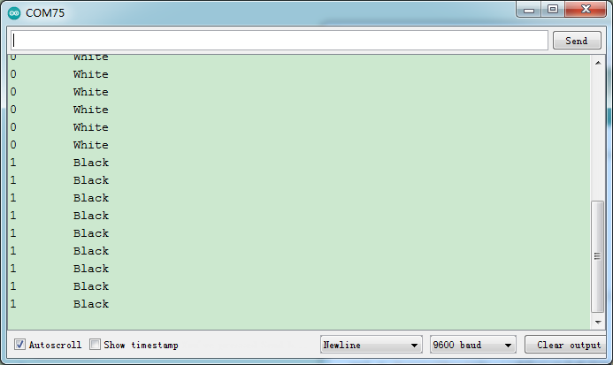
Test Result
Upload test code, wire up, open the monitor and set baud rate to 9600.
In the experiment, when the sensor doesn’t detect an object or detects a black object, the val is 1, and the monitor will display “Black” ; when a white object (can reflect light) is detected, the val is 0, and the monitor will display “White” ;
Project 8: Photo Interrupter
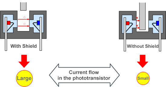
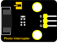
Description
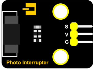
This kit contains a photo interrupter which mainly uses 1 ITR-9608 photoelectric switch. It is a photoelectric switch optical switch sensor.
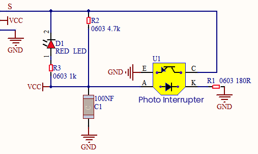
Working Principle
When the paper is put in the slot, C is connected with VCC and the signal end S of the sensor are high levels; then the red LED will be off. Otherwise, the red LED will be on.
Required Components
|
|
 |
|
|
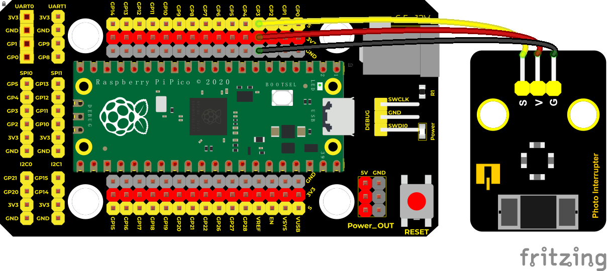
| Raspberry Pi Pico Board*1 | Raspberry Pi Pico Expansion Board*1 | Keyestudio DIY Photo Interrupter*1 | 3P Dupont Wire*1 | Micro USB Cable*1 |
Wiring Diagram
Test Code
/*
* Keyestudio 37 in 1 Starter Kit for Raspberry Pi Pico
* lesson 8
* Photo_Interrupt
* http://www.keyestudio.com
*/
int PushCounter = 0; //push counter variable
int State = 0; //output the current state
int lastState = 0; //output state of the sensor saved
**void setup() **
**void loop() **
}
lastState = State;//update
}
Code Explanation
Logic setting:
| Initial Setting | Set PushCounter to 0 | |
| Set State to 0 (value of the sensor) | ||
| Set lastState to 0 | ||
| when an object enters the slot | lastState is 0,State turns into 1; lastState turns into 1 | Set PushCounter to PushCounter+1 print the value of PushCounter |
| when the object leaves the slot | lastState is 1,State becomes 0,two data are not equal,lastState turns into 0. | PushCounterdoesn’t change; Don’t print the value of PushCounter |
| When the object goes through this slot again | lastState is 0, State becomes 1,two data are not equal,lastState turns into 1. | Set PushCounter to PushCounter+1 And print the value of PushCounter |
| When the object leaves this slot again | lastState is 1,State turns into 0,two data are not equal lastState turns into 0 | PushCounter doesn’t change; Don’t print the PushCounter value |
Test Result
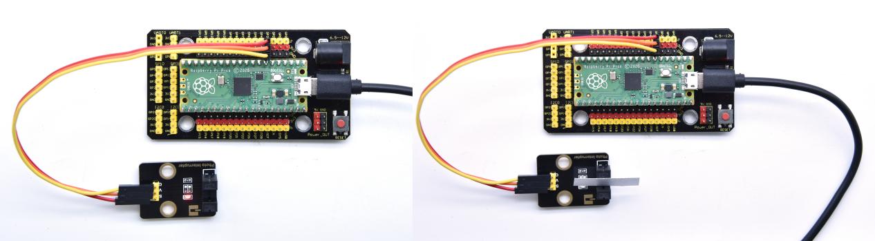
Wire up, upload test code, and the shell displays the PushCounter data. Every time when the object passes through the slot of the sensor, the PushCounter data will increase by 1 continuously, as shown below;
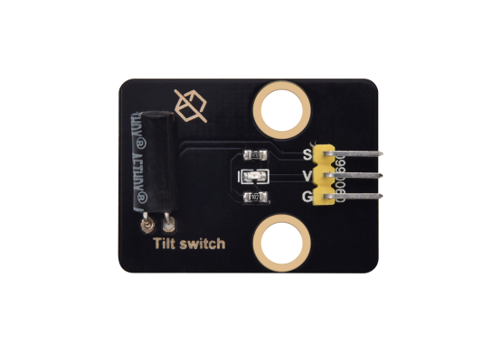
Project 9: Tilt Module

Overview
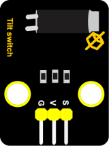
In this kit, there is a Keyestudio tilt sensor. The tilt switch can output signals of different levels according to whether the module is tilted. There is a ball inside. When the switch is higher than the horizontal level, the switch is turned on, and when it is lower than the horizontal level, the switch is turned off. This tilt module can be used for tilt detection, alarm or other detection.
Working Principle
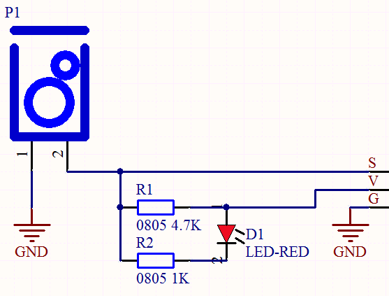
The working principle is pretty simple. When pin 1 and 2 of the ball switch P1 are connected, the signal S is low level and the red LED will light up; when they are disconnected, the pin will be pulled up by the 4.7K R1 and make S a high level, then LED will be off.
Components
|
|
 |
|
|
| Raspberry Pi Pico Board*1 | Raspberry Pi Pico Shield*1 | Keyestudio Tilt Sensor*1 |
3P Dupont Wire*1 | Micro USB Cable*1 |
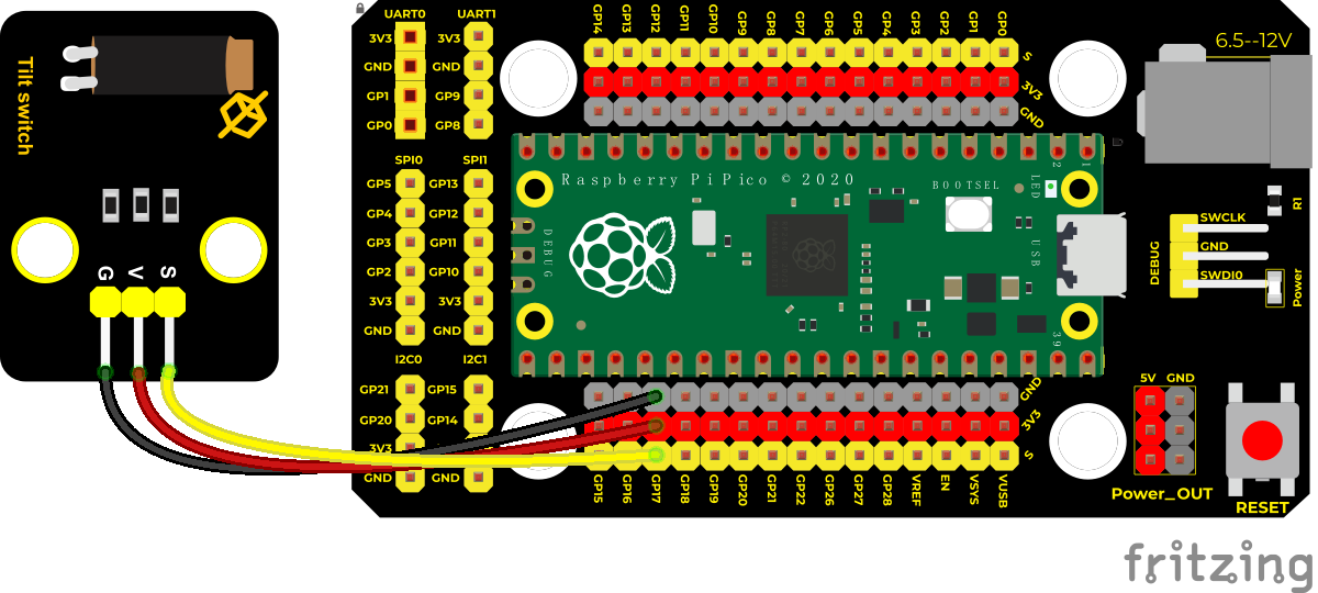
Wiring Diagram
Test Code
/*
* Keyestudio 42 in 1 Starter Kit for Raspberry Pi Pico
* lesson 9
* Tilt switch
* http://www.keyestudio.com
*/
int val; //save the output level value of tilt sensor
**void setup() **
**void loop() **
Test Result
Upload the code power up by a USB cable, open the serial monitor and set baud rate to 9600.
Make the tilt module incline to one side, the red LED on the module will be off and the monitor will display“1”. In contrast, if you make it incline the other side, the red LED will light up and the monitor will display“0”.
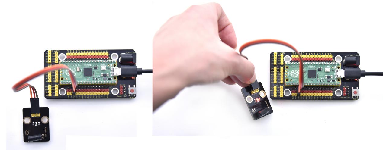
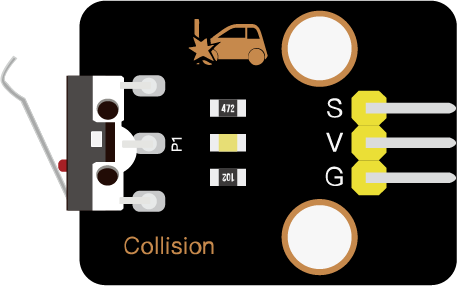
Project 10: Collision Sensor

Description
The collision sensor uses a tact switch. This sensor is often used as a limit switch in 3D printers. In the experiment, we judge whether the sensor shrapnel is pressed down by reading the high and low levels of the S terminal on the module; and, we display the test results in the shell.
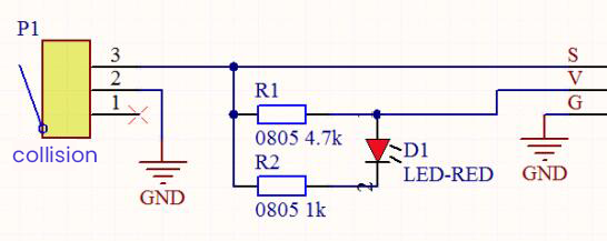
Working Principle
It mainly uses a tact switch. When the shrapnel of the tact switch is pressed, 2 and 3 are connected, the signal terminal S is low level, and the red LED on the module lights up; when the touch switch is not pressed, 2 and 3 are not connected, and 3 is pulled up to a high level by the 4.7K resistor R1, that is, the sensor signal terminal S is a high level, and the built-in red LED will be off at this time.
Components Required
|
|
|
|
|
| Raspberry Pi Pico Board*1 | Raspberry Pi Pico Expansion Board*1 | Keyestudio Collision Sensor*1 | 3P Dupont Wire*1 | Micro USB Cable*1 |
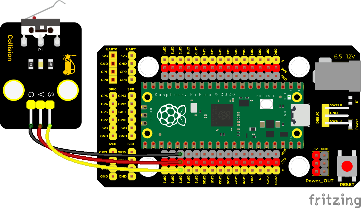
Wiring Diagram
Test Code
/*
Keyestudio 42 in 1 Starter Kit for Raspberry Pi Pico
lesson 10
collision sensor
http://www.keyestudio.com
*/
int val = 0;
**void setup() **
**void loop() **
**else **
}
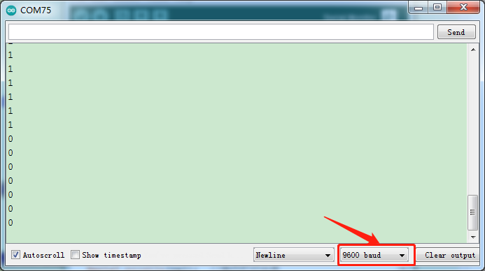
Test Result
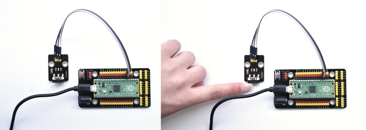
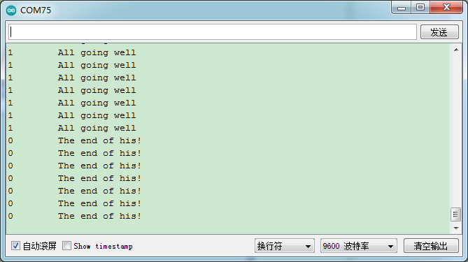
Run the test code, the shell displays the corresponding data and characters. In the experiment, when the shrapnel on the sensor is pressed down, val is 0, the red LED of the module is on, and “The end of his!” is printed; when the shrapnel is released, the val is 1, the red LED of the module is off, and “All going well” is printed. !” character, as shown below.
Project 11: Hall Sensor

Description
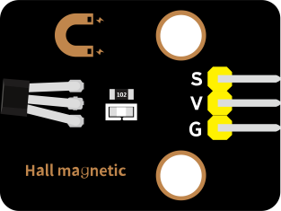
In this kit, there is a Hall sensor which mainly adopts a A3144 linear Hall element. The element P1 is composed of a voltage regulator, a Hall voltage generator, a differential amplifier, a Schmitt trigger, a temperature compensation circuit and an open-collector output stage. In the experiment, we use the Hall sensor to detect the magnetic field and display the test results on the shell.
Working Principle
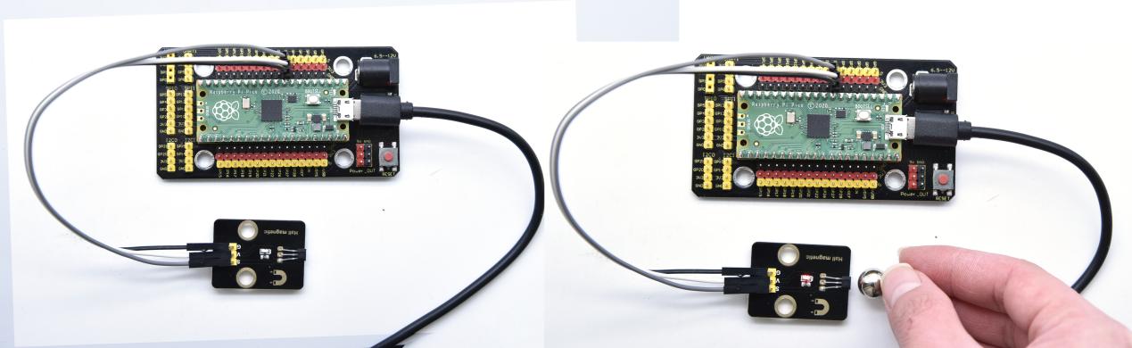
When the sensor detects no magnetic field or a north pole magnetic field, the signal terminal will be high level; when it senses a south pole magnetic field, the signal terminal will be low levels.
The stronger the magnetic field strength is, induction distance is longer.
Required Components
|
|
 |
|
|
| Raspberry Pi Pico Board*1 | Raspberry Pi Pico Expansion Board*1 | Keyestudio DIY Hall Sensor*1 | 3P Dupont Wire*1 | Micro USB Cable*1 |
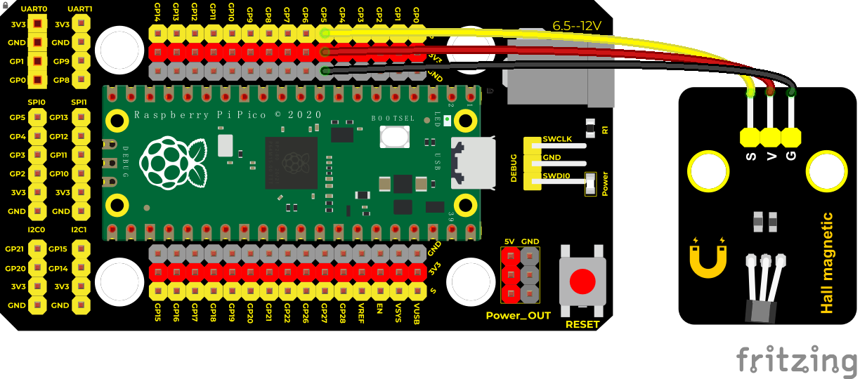
Wiring Diagram
Test Code
/*
* Keyestudio 42 in 1 Starter Kit for Raspberry Pi Pico
* lesson 11
* Hall magnetic
* http://www.keyestudio.com
*/
int val = 0;
int hallPin = 5; //the pin of the hall sensor is connected to port 5
**void setup() **
**void loop() **
**else **
delay(100);
}
Test Result
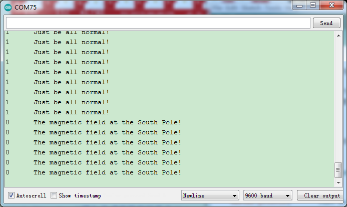
Upload the test code, open the monitor and set baud rate to 9600.
when the sensor detects no magnetic fields or the north pole magnetic field, the monitor l will show“1 Just be all normal!”and the LED on the sensor will be off; When it detects the south pole magnetic field,“0 The magnetic field at the South Pole!”and the LED on the sensor will be on.
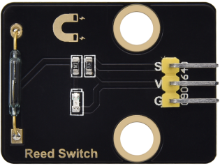
Project 12: Reed Switch Module

Overview
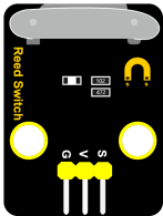
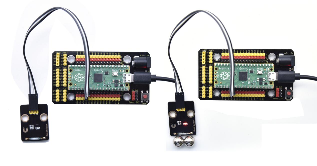
In this kit, there is a Keyestudio reed switch module, which mainly uses a MKA10110 green reed component.
The reed switch is the abbreviation of the dry reed switch. It is a passive electronic switch element with contacts.
It has the advantages of simple structure, small size and easy control.
Its shell is a sealed glass tube with two iron elastic reed electric plates.
In the experiment, we will determine whether there is a magnetic field near the module by reading the high and low level of the S terminal on the module; and, we display the test result in the shell.
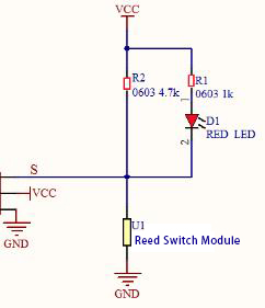
Working Principle
Reed switch is an abbreviation of the dry reed contacts a passive
electronic switching elements, and has the advantages of simple structure, small size and ease of control, its shell is a sealed glass tube, the tubes are installed two iron elastic reed plate, but also filling called rhodium metal inert gas. In peacetime, the glass tube in the two reeds made of special materials are separated. When a magnetic substance close to the glass tube, in the role of the magnetic field lines, the pipe within the two reeds are magnetized to attract each other in contact, the reed will suck together, so that the junction point of the connected circuit communication. After the disappearance of the outer magnetic reed because of their flexibility and separate, the line is disconnected. Therefore, as a use of the magnetic field signals to control the line switching device, reed tube can be used as a sensor for counting the number, spacing, etc., and also are widely used in a variety of communication devices.
Components
|
|
 |
|
|
| Raspberry Pi Pico Board*1 | Raspberry Pi Pico Shield*1 | Keyestudio Reed Switch Module*1 | 3P Dupont Wire*1 | Micro USB Cable*1 |
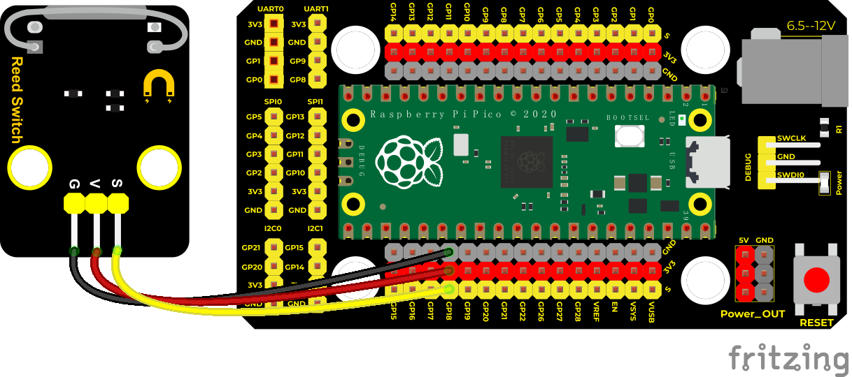
Wiring Diagram
Test Code
/*
* Keyestudio 42 in 1 Starter Kit for Raspberry Pi Pico
* lesson 12
* Reed Switch
* http://www.keyestudio.com
*/
int val = 0;
int reedPin = 18; ///the signal pin of reed switch module is GP18
**void setup() **
**void loop() **
**else **
}
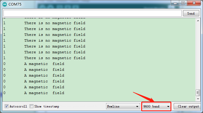
Test Result
Upload the code power up by a USB cable, open the serial monitor and set baud rate to 9600. When the sensor detects a magnetic field, val is 0 and the red LED of the module lights up, “A magnetic field” will be displayed; when no magnetic field is detected, val is 1, and the LED on the module goes out, “There is no magnetic field” will be shown, as shown below.
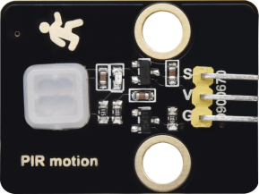
Project 13: PIR Motion Sensor
Overview
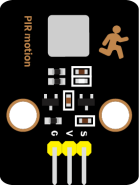
In this kit, there is a Keyestudio PIR motion sensor, which mainly uses an RE200B-P sensor elements. It is a human body pyroelectric motion sensor based on pyroelectric effect, which can detect infrared rays emitted by humans or animals, and the Fresnel lens can make the sensor’s detection range farther and wider.
In the experiment, we determine if there is someone moving nearby by reading the high and low levels of the S terminal on the module. The detected results will be displayed on the Shell.
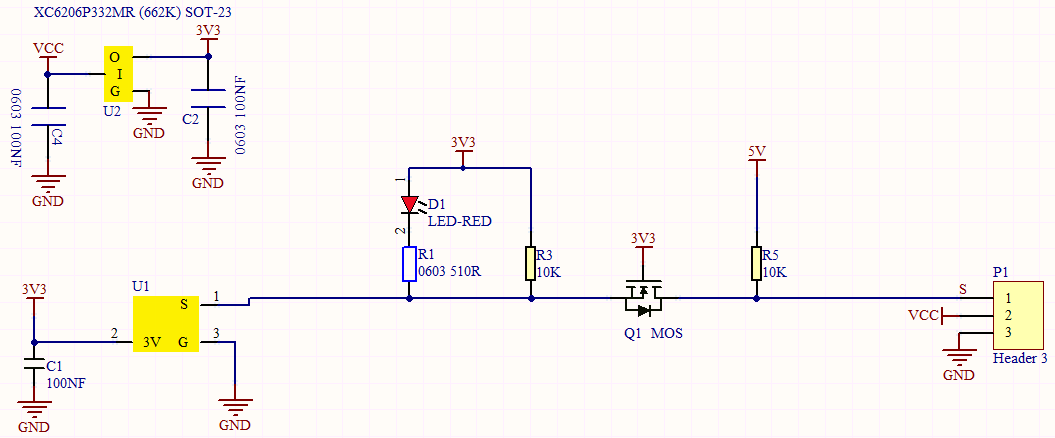
Working Principle
The upper left part is voltage conversion(VCC to 3.3V). The working voltage of sensors we use is 3.3V, therefore we can’t use 5V directly. The voltage conversion circuit is needed.
When no person is detected or no infrared signal is received, and pin 1 of the sensor outputs low level. At this time, the LED on the module will light up and the MOS tube Q1 will be connected and the signal terminal S will detect Low levels.
When one is detected or an infrared signal is received, and pin 1 of the sensor outputs a high level. Then LED on the module will go off, the MOS tube Q1 is disconnected and the signal terminal S will detect high levels.
Components
|
|
 |
|
|
| Raspberry Pi Pico Board*1 | Raspberry Pi Pico Shield*1 | Keyestudio PIR Motion Sensor*1 | 3P Dupont Wire*1 | Micro USB Cable*1 |
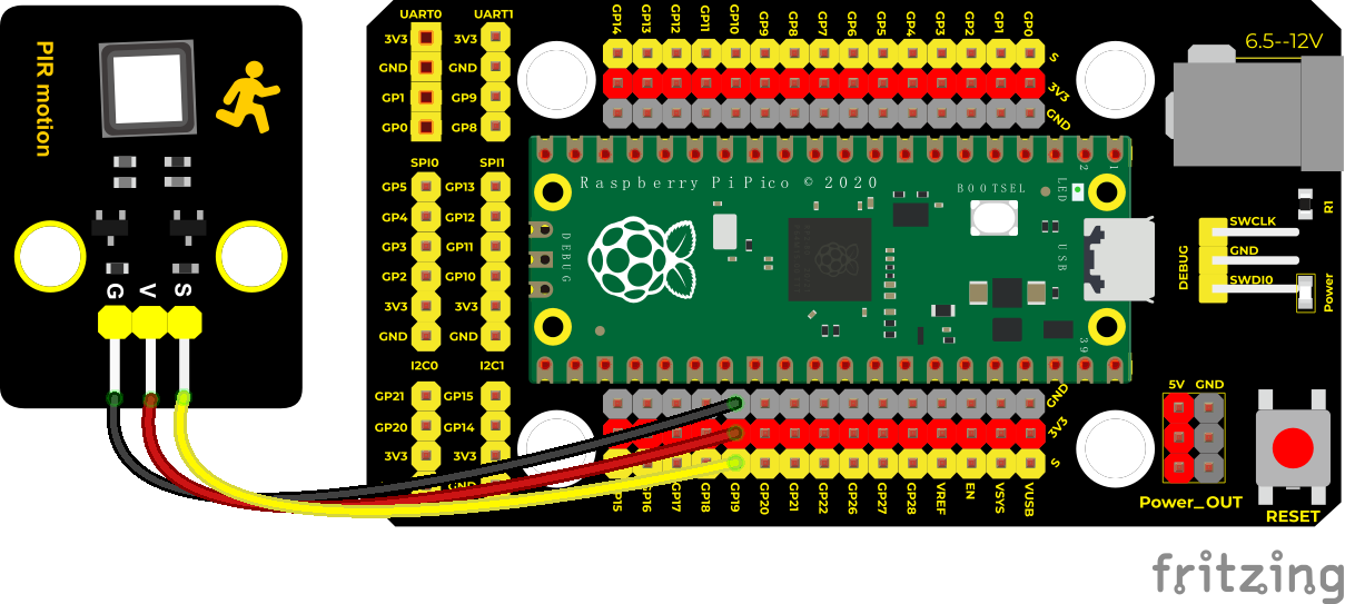
Wiring Diagram
Test Code
/*
* Keyestudio 42 in 1 Starter Kit for Raspberry Pi Pico
* lesson 13
* PIR motion
* http://www.keyestudio.com
*/
int val = 0;
int pirPin = 19; //set the pin of PIR motion sensor to GP19
**void setup() **
**void loop() **
**else **
}
Test Result
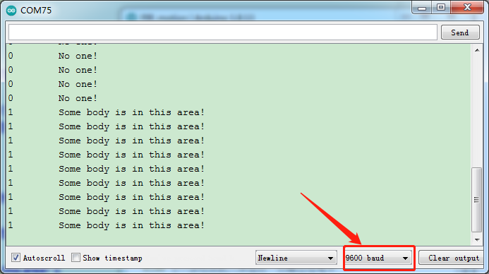
Upload the code power up by a USB cable, open the serial monitor and set baud rate to 9600. When the sensor detects someone nearby, value is 1, the LED will go off and the monitor will show“Somebody is in this area!”. In contrast, the value is 0, the LED will go up and“0 No one!”will be shown.
Project 14: Active Buzzer

Overview
In this kit, it contains an active buzzer module and a power amplifier module (the principle is equivalent to a passive buzzer). In this experiment, we control the active buzzer to emit sounds. Since it has its own oscillating circuit, the buzzer will automatically sound if given large voltage.
Working Principle
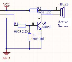
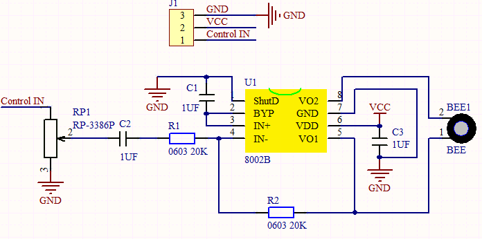
From the schematic diagram, the pin of buzzer is connected to a resistor R2 and another port is linked with a NPN triode Q1. So, if this triode Q1 is powered, the buzzer will sound.
If the base electrode of the triode connected to the R1 resistor is a high level, the triode Q1 will be connected.If the base electrode is pulled down by the resistor R3, the triode is disconnected.
When we output a high level from the IO port to the triode, the buzzer will emit sounds; if outputting low levels, the buzzer won’t emit sounds.
Components
|
|
 |
|
|
| Raspberry Pi Pico Board*1 | Raspberry Pi Pico Shield*1 | Keyestudio Active Buzzer*1 | 3P Dupont Wire*1 | Micro USB Cable*1 |
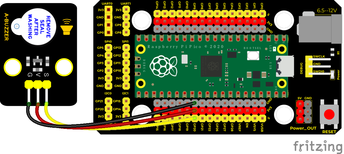
Wiring Diagram
Test Code
/*
* Keyestudio 42 in 1 Starter Kit for Raspberry Pi Pico
* lesson 14
* Active buzzer
* http://www.keyestudio.com
*/
int buzzer = 20; //set the pin of the active sensor to GP20
**void setup() **
**void loop() **
Code Explanation
In the experiment, we set the pin number to 20. When setting to high, the active buzzer will beep; when setting to low, the active buzzer will stop emitting sounds
Test Result
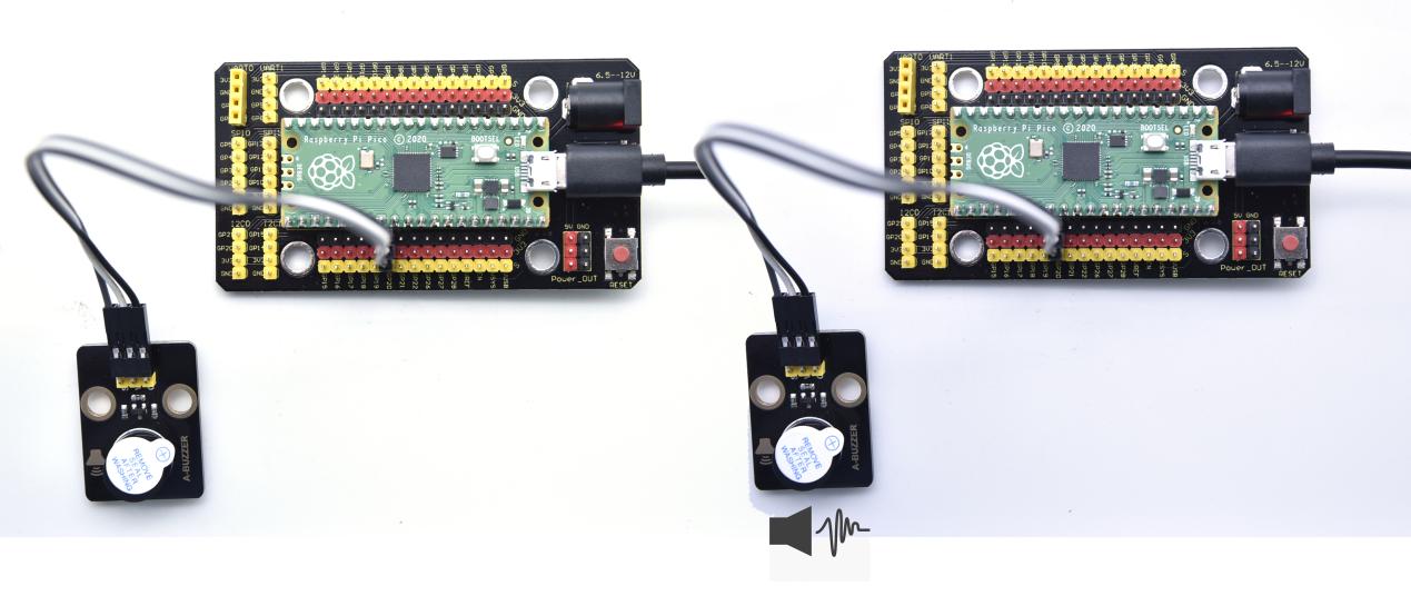
Upload the code and power on. The active buzzer will emit sound for 1 second, and stop for 1 second.
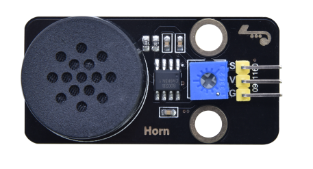
Project 15: 8002b Audio Power Amplifier

Overview
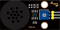
In this kit, there is a Keyestudio 8002b audio power amplifier. The main components of this module are an adjustable potentiometer, a speaker, and an audio amplifier chip;
The main function of this module is: it can amplify the output audio signal, with a magnification of 8.5 times, and play sound or music through the built-in low-power speaker, as an external amplifying device for some music playing equipment.
In the experiment, we used the 8002b power amplifier speaker module to emit sounds of various frequencies.
Working Principle
In fact, it is similar to a passive buzzer. The active buzzer has its own oscillation source.Yet, the passive buzzer does not have internal oscillation. When controlling the circuit, we need to input square waves of different frequencies to the positive pole of the component and ground the negative pole to control the buzzer to chime sounds of different frequencies.
Components
|
|
 |
|
|
| Raspberry Pi Pico Board*1 | Raspberry Pi Pico Shield*1 | Keyestudio 8002b Audio Power Amplifier*1 | 3P Dupont Wire*1 | Micro USB Cable*1 |
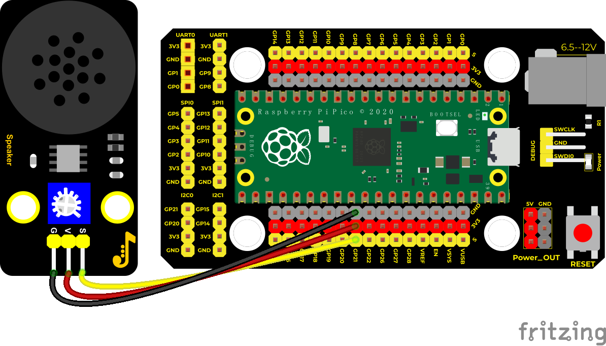
Wiring Diagram
Test Code/*
* Keyestudio 42 in 1 Starter Kit for Raspberry Pi Pico
* lesson 15
* Passive buzzer
* http://www.keyestudio.com
*/
int beeppin = 21; //set the pin of the power amplifier to GP21
**void setup() **
**void loop() **
Code Explanation
In the experiment, we use the function tone(). We set pin to 21. Function tone generates waves of frequency.
Test Result
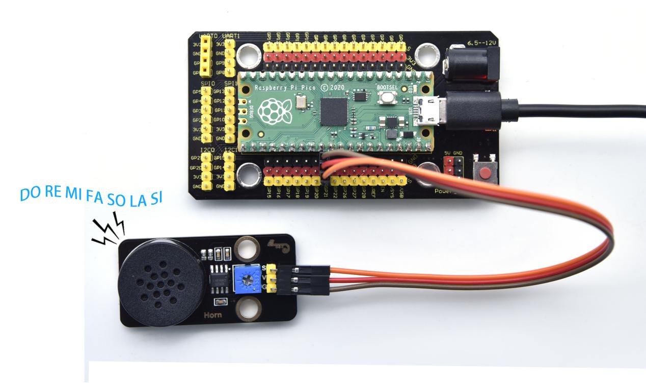
Upload the test code successfully and power on.The power amplifier module will emit the sound of the corresponding frequency corresponding to the beat:
DO for one beat, Re for 0.75 beat, Mi for 0.625, Fa for 1/2 beat, So for 0.375 beat, La for 1/4 beat and Si for 0.125 beat
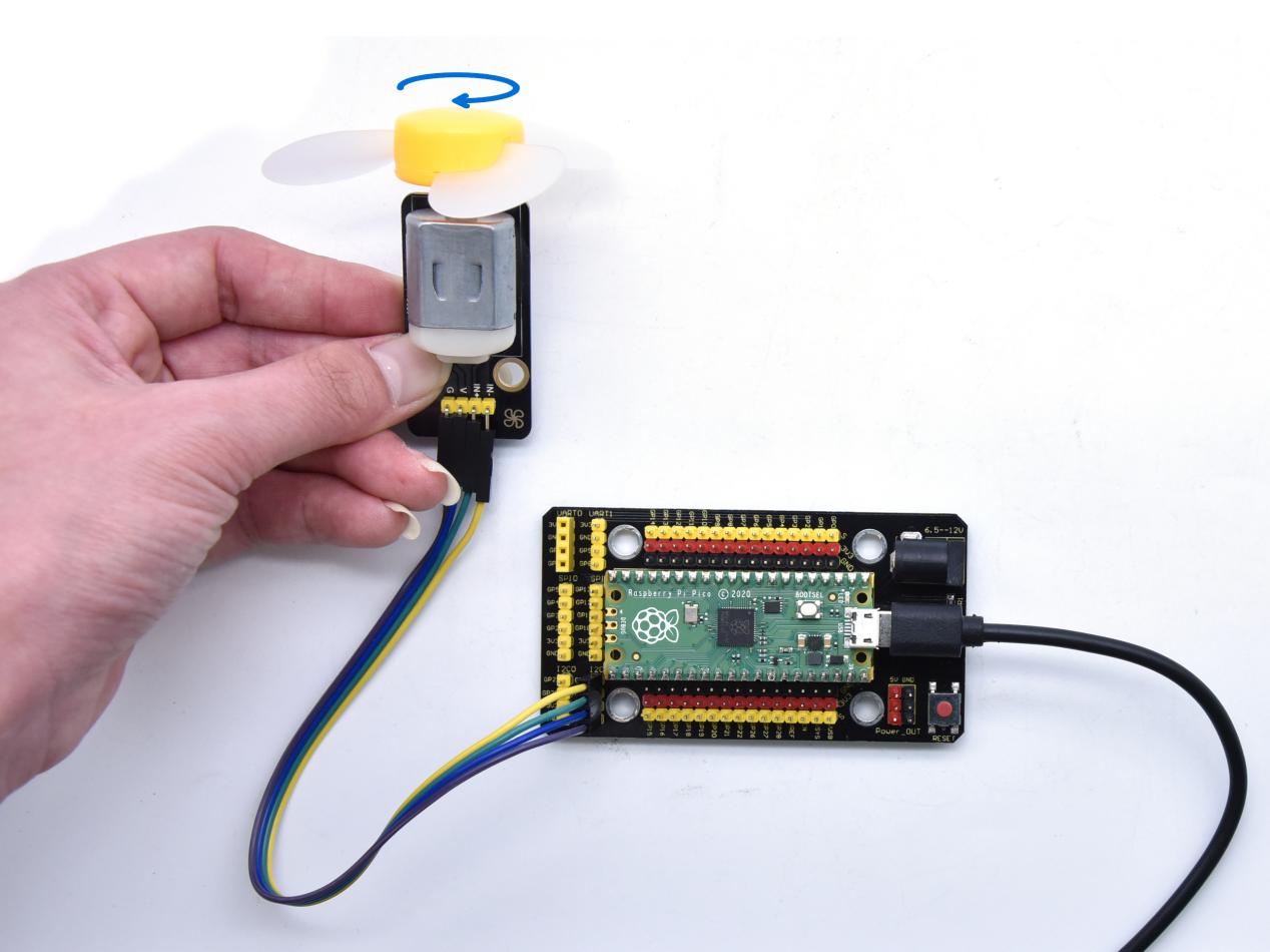
Project 16: 130 Motor

Description
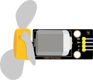
The 130 motor driver module is compatible with servo motors, which has high efficiency and good quality fans.
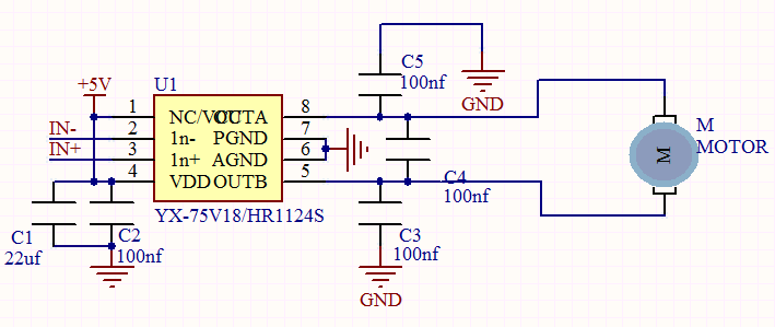
It adopts a HR1124S motor control chip. HR1124S is a single-channel H-bridge driver chip for DC motor solutions. In addition, this chip has low standby current and low quiescent current.
The module is compatible with various single-chip control boards. In the experiment, we can control the rotation direction of the motor by outputting the voltage directions of the two signal terminals IN+ and IN- to make the motor rotate.
Working Principle
The chip is used to help drive the motor.
We can’t drive it with a triode or an IO port due to its a large current of need. It is very simple to make the motor rotate. Just apply voltage to both ends of the motor. The direction of the motor is different in different voltage directions. Within the rated voltage, the higher the voltage, the faster the motor rotates; on the contrary, the lower the voltage, the slower the motor rotates, or even unable to rotate.
So we can use the PWM port to control the speed of the motor. We haven’t learned PWM here, so we use the high and low levels to control the motor first.
Components
|
|
 |
 |
|
| Raspberry Pi Pico Board*1 | Raspberry Pi Pico Expansion Board*1 | keyestudio DIY 130 Motor*1 | 4P Dupont Wire*1 | Micro USB Cable*1 |
Note: the motor is separated with its fan, you need to assemble it first.
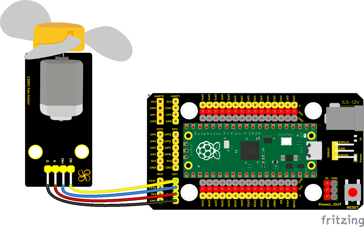
Wiring Diagram
Test Code
/*
* Keyestudio 42 in 1 Starter Kit for Raspberry Pi Pico
* lesson 16
* 130DC Fan motor
* http://www.keyestudio.com
*/
//define two pins of the motor as 14 and 15
int INA = 14;
int INB = 15;
**void setup() **
**void loop() **
Code Explanation
Set pins to 14 and 15, when the pin 14 outputs high levels and the pin 15 outputs low levels, the motor will rotate counterclockwise; when both pins are set to low, the motor stops rotating.
Test Result
Burn the test 130 motor code, and connect the wires according to the Wiring Diagram; after power-on, the fan rotates counterclockwise for 2 seconds; stops for 1 second; rotates clockwise for 2 seconds; stops for 1 second; cycle alternately.
Wire up, upload test code and test the 130 motor, the fan will rotate counterclockwise for 2 seconds, stop for 1 second and clockwise for 2 seconds and stop for 1 second; cycle alternately.
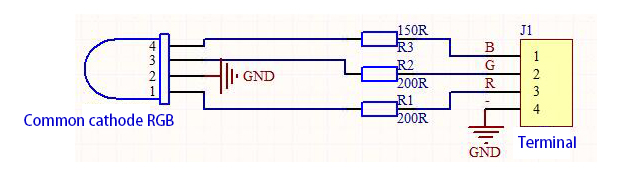
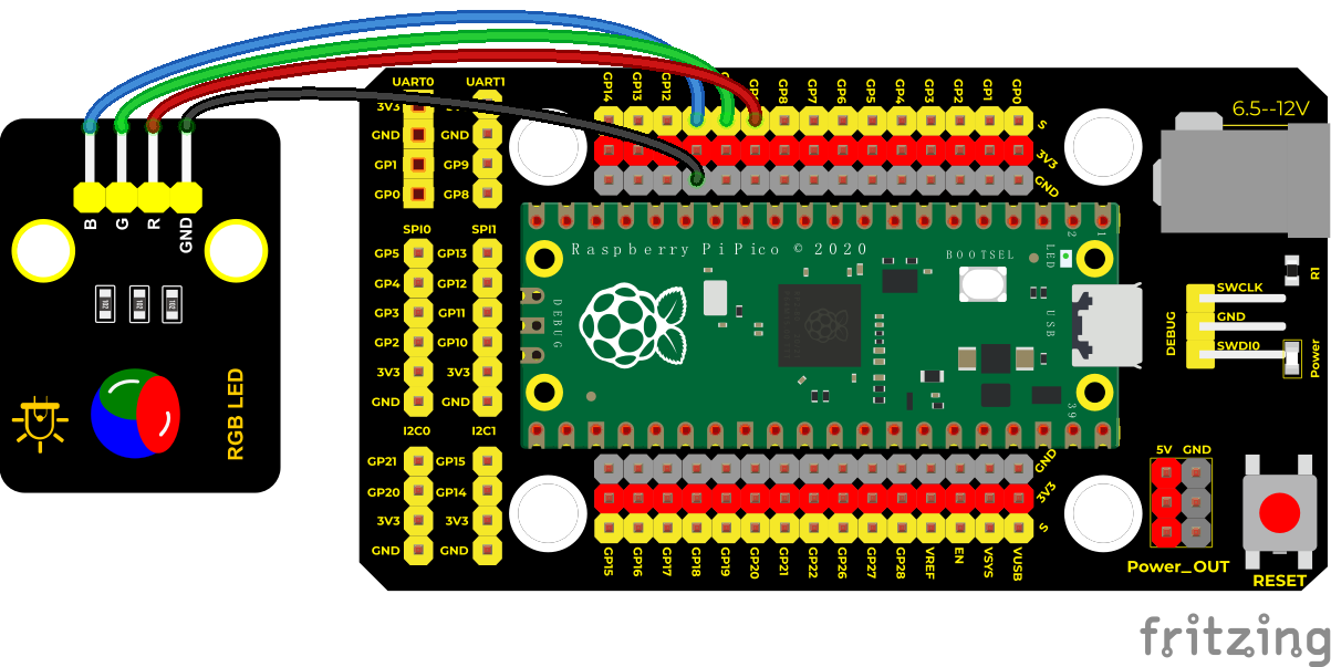
Project 17: RGB Module

Overview
Among these modules is a RGB module. It adopts a F10-full color RGB foggy common cathode LED. We connect the RGB module to the PWM port of MCU and the other pin to GND(for common anode RGB, the rest pin will be connected to VCC). So what is PWM?
PWM is a means of controlling the analog output via digital means. Digital control is used to generate square waves with different duty cycles (a signal that constantly switches between high and low levels) to control the analog output.In general, the input voltages of ports are 0V and 5V. What if the 3V is required? Or a switch among 1V, 3V and 3.5V? We cannot change resistors constantly. For this reason, we resort to PWM.
For Arduino digital port voltage outputs, there are only LOW and HIGH levels, which correspond to the voltage outputs of 0V and 5V respectively. You can define LOW as“0”and HIGH as“1’, and let the Arduino output five hundred‘0’or“1”within 1 second. If output five hundred‘1’, that is 5V; if all of which is‘0’,that is 0V; if output 250 01 pattern, that is 2.5V.
This process can be likened to showing a movie. The movie we watch are not completely continuous. Actually, it generates 25 pictures per second, which cannot be told by human eyes. Therefore, we mistake it as a continuous process. PWM works in the same way. To output different voltages, we need to control the ratio of 0 and 1. The more‘0’or‘1’ output per unit time, the more accurate the control.
Working Principle
For our experiment, we will control the RGB module to display different colors through three PWM values.
Components
|
|
 |
|
|
| Raspberry Pi Pico Board*1 | Raspberry Pi Pico Shield*1 | Keyestudio Common Cathode RGB Module *1 | 4P Dupont Wire*1 | Micro USB Cable*1 |
Test Code
Code 1:
/*
* Keyestudio 42 in 1 Starter Kit for Raspberry Pi Pico
* lesson 17.1
* rgb_1
* rgb_1
* http://www.keyestudio.com
*/
int redPin = 9; //the red LED is connected to GP9
int greenPin = 10; //the green LED is connected to GP10
int bluePin = 11; //the blue LED is connected to GP11
void setup()
void loop()
Code 2:
/*
* Keyestudio 42 in 1 Starter Kit for Raspberry Pi Pico
* lesson 17.2
* rgb_2
* http://www.keyestudio.com
*/
int redPin = 9; //the red LED is connected to GP9
int greenPin = 10; //the green LED is connected to GP10
int bluePin = 11; //the blue LED is connected to GP11
**void setup() **
**void loop() **
Code Explanation
Code 1:
For code 1, RGB stands for corresponding ports of red, green and blue.
According to the connection diagram, GP9,GP10 and GP11 are connected, then we set 9, 10 and 11 and HOGH and LOW. If setting to HIGH, the LED will light up.
RGB LED shows red color for 1s, green color for 1s, blue color for 1s
Code 2:
1. In code 2, we use PWM output. According to the wiring diagram, we connect GP9, GP10 and GP11 and set to 9 10 11.
(Note: The PWM output of pico is normally 0~65535, and we use adjust it to 0~255).
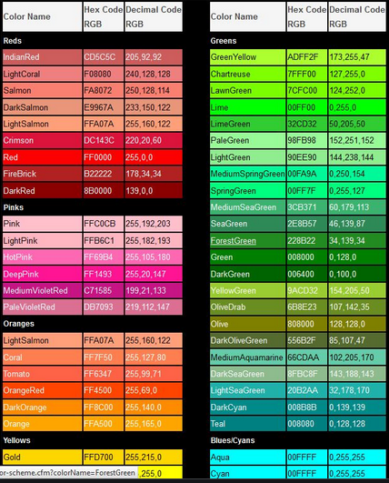
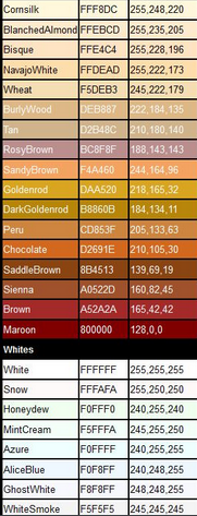
In the experiment, we adjust the ratio of red, green and blue colors on the RGB LED by setting the corresponding values, so as to control the RGB LED to display corresponding colors. So theoretically, there are 256*256*256 colors that can be set (for details, please refer to the common RGB color table below)
RGB Color Chart
Test Result
Upload the code 1, the RGB on the module will show red, green and blue color with an interval of 1s.
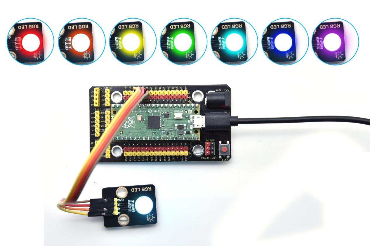
Upload the code 2, the RGB on the module will show red, orange, yellow, green, cyan-blue, blue, purple and white color with an interval of 1s.
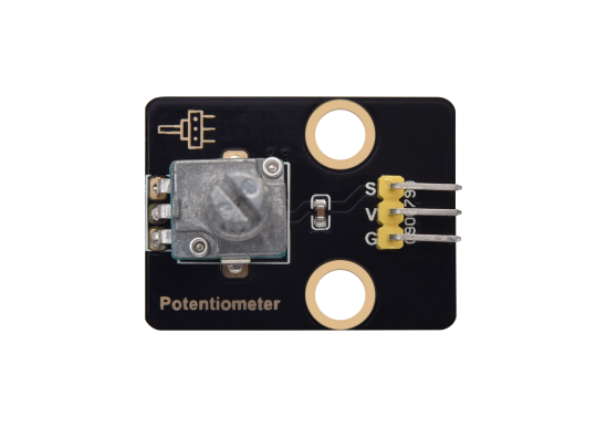
Project 18: Potentiometer

Overview
The following we will introduce is the Keyestudio rotary potentiometer which is an analog sensor.
The digital IO ports can read the voltage value between 0 and 3.3V and the module only outputs high levels. However, the analog sensor can read the voltage value through ADC analog ports(GP26~GP28) on the pico board.
In the experiment, we will display the test results on the Shell.

Working Principle
It uses a 10K adjustable resistor. We can change the resistance by rotating the potentiometer. The signal S can detect the voltage changes(0-3.3V) which are analog quantity
Components
|
|
 |
|
|
| Raspberry Pi Pico Board*1 | Raspberry Pi Pico Shield*1 | Keyestudio Rotary Potentiometer*1 | 3P Dupont Wire*1 | Micro USB Cable*1 |
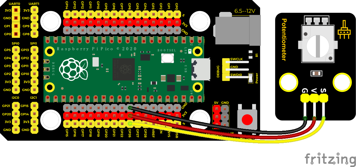
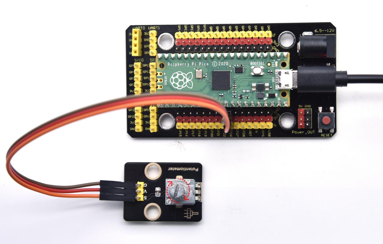
Wiring Diagram
Test Code
/*
* Keyestudio 42 in 1 Starter Kit for Raspberry Pi Pico
* lesson 18
* Rotary potentiometer
* http://www.keyestudio.com
*/
int analogVal = 0;
int resPin = 26; //the potentiometer is connected to ADC0
**void setup() **
**void loop() **
Code Explanation
analogVal means analog value. The rotary potentiometer outputs analog values(0~4095), therefore, we set pins to analog ports. For example, we connect to ADC0(GP26)
analogRead(pin): read the value of the specified analog pin. The pico board contains a multi-channel, 12-bit converter. This means that it will map the input voltage between 0 and the working voltage (5V or 3.3V ) to an integer value between 0 and 4095. For example, this will produce a resolution among readings: 3.3V/4096 stands for 0.0008V per unit.
Pin: the name of analog input pin. GP26 is connected to GP28, GP29 measures VSYS voltage and ADC4 measures the internal temperature.
Test Result
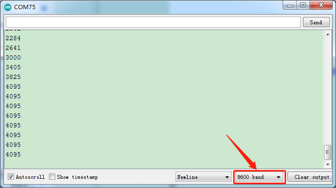
Upload the code power up by a USB cable, open the serial monitor and set baud rate to 9600.
In the experiment, rotate the potentiometer clockwise, the analog value increases, and turn the potentiometer counterclockwise, the analog value decreases(0-4095), as shown in the figure below.
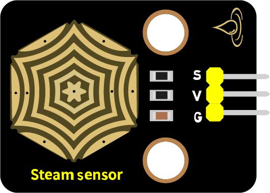
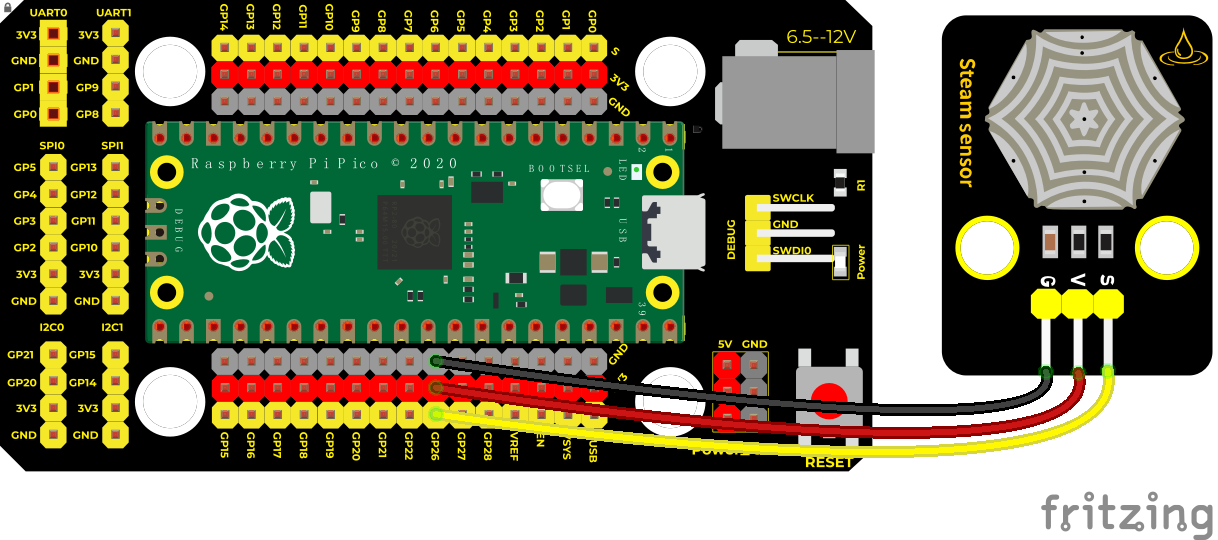
Project 19: Steam Sensor

Description
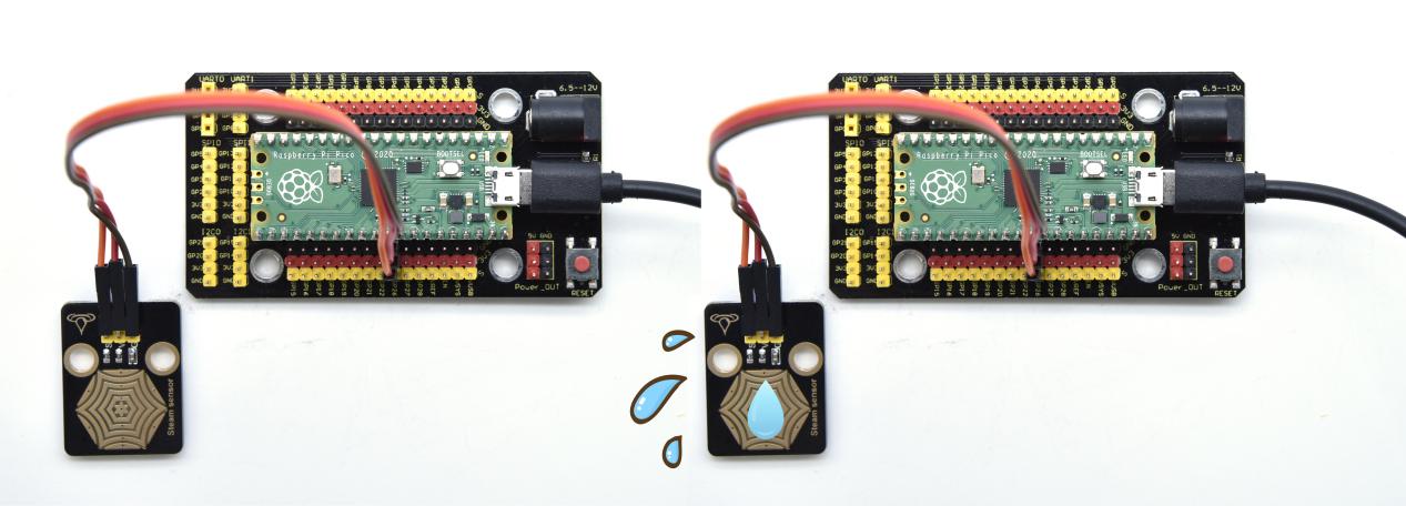
This is a commonly used steam sensor. Its principle is to detect the amount of water by bare printed parallel lines on the circuit board. The more the water is, the more wires will be connected. As the conductive contact area increases, the output voltage will gradually rise. It can detect water vapor in the air as well. The steam sensor can be used as a rain water detector and level switch. When the humidity on the sensor surface surges, the output voltage will increase.
In the experiment, we connect the signal terminal (S terminal) of the sensor to the analog port of the pico development board. The analog value detected will be displayed on the serial monitor.
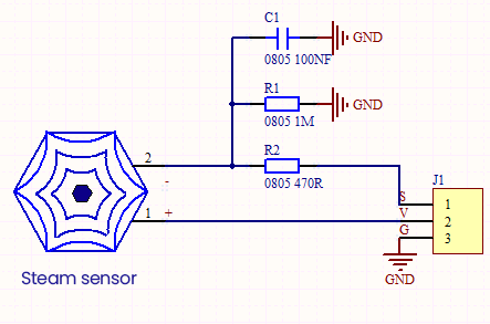
Working Principle
Its principle is to detect the amount of water through the exposed printed parallel lines on the circuit board. The more water there is, the more wires will be connected, and the conductive contact area increases. The voltage output by pin 2 will gradually increase. The larger the analog value detected by the signal terminal S is.
It can also detect steam in the air. Two position holes are used to install on the other devices
Required Components
|
|
|
|
|
| Raspberry Pi Pico Board*1 | Raspberry Pi Pico Expansion Board*1 | Keyestudio DIY Steam Sensor *1 | 3P Dupont Wire*1 | Micro USB Cable*1 |
Test Code
/*
* Keyestudio 42 in 1 Starter Kit for Raspberry Pi Pico
* lesson 19
* Steam sensor
* http://www.keyestudio.com
*/
int val = 0;
int Water = 26; //the pin of the steam sensor is 26
**void setup() **
**void loop() **
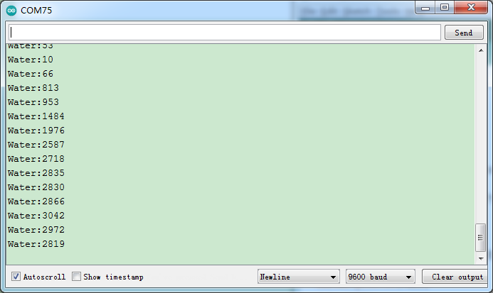
Test Result
Wire up, run the test code , power up and set baud rate to 9600. The more water volume, the greater the output voltage and the analog value, as shown below.
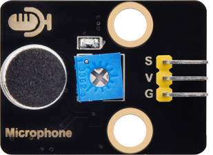
Project 20: Sound Sensor

Overview
In this kit, there is a sound sensor. In the experiment, we test the analog value corresponding to the sound level in the current environment with it. The louder the sound, the larger the analog value;
Working Principle
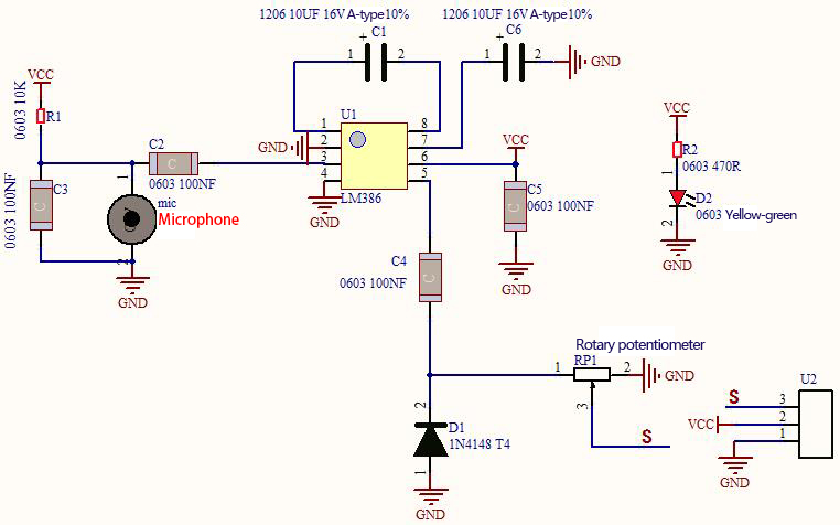
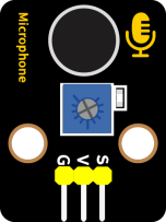
It uses a high-sensitive microphone component and an LM386 chip.
We build the circuit with the LM386 chip and amplify the sound through the high-sensitive microphone. In addition, we can adjust the sound volume by the potentiometer. Rotate it clockwise, the sound will get louder.
Components
|
|
 |
|
|
| Raspberry Pi Pico Board*1 | Raspberry Pi Pico Shield*1 | Keyestudio Sound Sensor*1 | 3P Dupont Wire*1 | Micro USB Cable*1 |
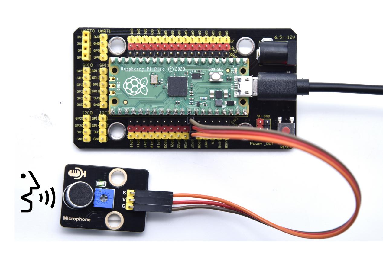
Wiring Diagram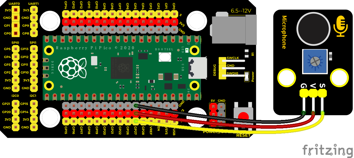
Test Code
/*
* Keyestudio 42 in 1 Starter Kit for Raspberry Pi Pico
* lesson 20
* http://www.keyestudio.com
*/
int val = 0;
int Microphone = 27; //microphone is connected to ADC1
**void setup() **
**void loop() **
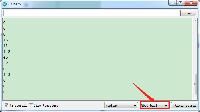
Test Result
Upload the code power up by a USB cable, open the serial monitor and set baud rate to 9600. Rotate clockwise the potentiometer and speak at the MIC. Then you can see the analog value get larger, as shown below
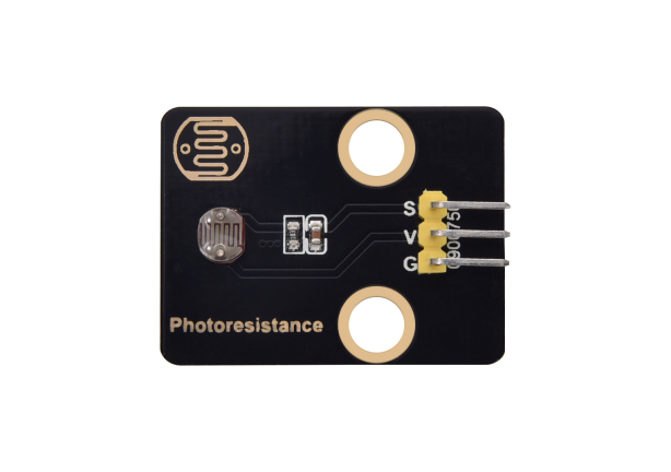
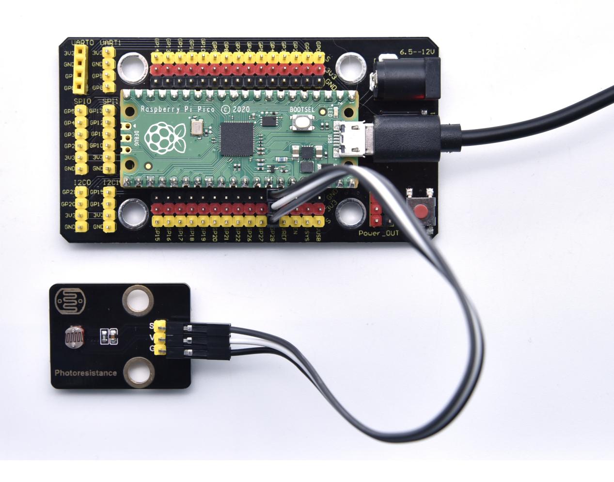
Project 21: Photoresistor
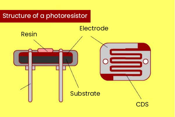
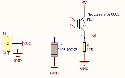
Description
In this kit, there is a photoresistor which consists of photosensitive resistance elements. Its resistance changes with the light intensity. Also, it converts the resistance change into a voltage change through the characteristic of the photosensitive resistive element. When wiring it up, we interface its signal terminal (S terminal) with the analog port of pico , so as to sense the change of the analog value, and display the corresponding analog value in the shell.
Working Principle
If there is no light, the resistance is 0.2MΩ and the detected voltage at the terminal 2 is close to 0. When the light intensity increases, the resistance of photoresistor and detected voltage will diminish.
Components
|
|
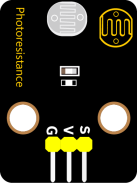 |
|
|
| Raspberry Pi Pico Board*1 | Raspberry Pi Pico Shield*1 | Keyestudio Photoresistor*1 | 3P Dupont Wire*1 | Micro USB Cable*1 |
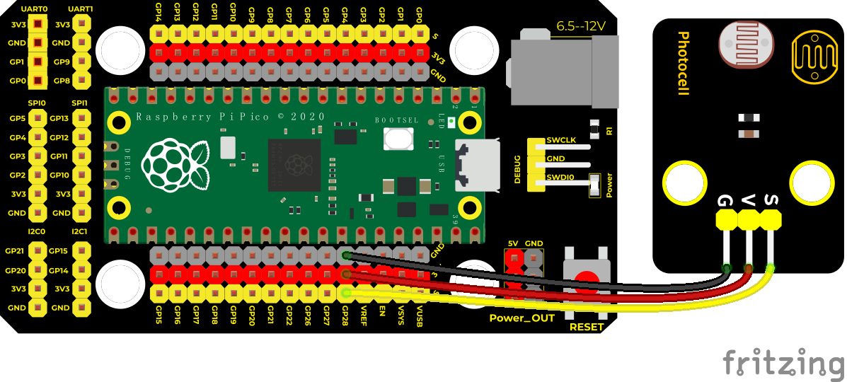
Wiring Diagram
Test Code
/*
* Keyestudio 42 in 1 Starter Kit for Raspberry Pi Pico
* lesson 21
* Photoresistance
* http://www.keyestudio.com
*/
int val = 0;
int photoPin = 28; //analog port ADC2 of photoresistor
**void setup() **
**void loop() **
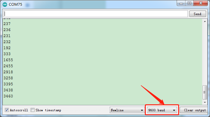
Test Result
Upload the code power up by a USB cable, open the serial monitor and set baud rate to 9600. When the light intensity gets stronger, the analog value will get larger, as shown below;
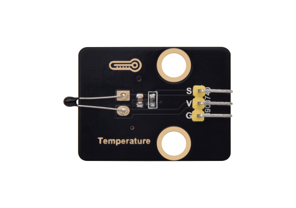
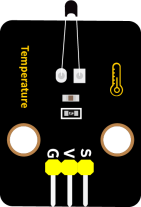
Project 22: NTC-MF52AT Thermistor

Overview
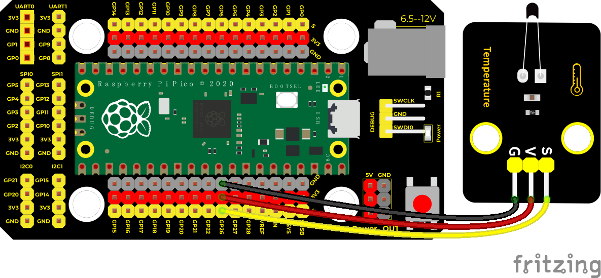
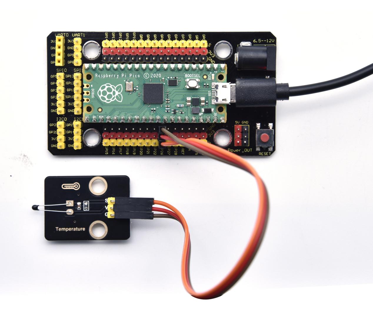
In the experiment, there is a NTC-MF52AT analog thermistor. We connect its signal terminal to the analog port of the Raspberry Pi Pico Board and read the corresponding analog value.
We can use analog values to calculate the temperature of the current environment through specific formulas. Since the temperature calculation formula is more complicated, we only read the corresponding analog value.
Working Principle
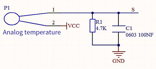
This module mainly uses NTC-MF52AT thermistor elements. The NTC-MF52AT thermistor element can sense the changes of the surrounding environment temperature. Resistance changes with the temperature, causing the voltage of the signal terminal S to change.
This sensor uses the characteristics of NTC-MF52AT thermistor element to convert resistance changes into voltage changes.
Components
|
|
 |
|
|
| Raspberry Pi Pico Board*1 | Raspberry Pi Pico Shield*1 | Keyestudio NTC-MF52AT Thermistor*1 | 3P Dupont Wire*1 | Micro USB Cable*1 |
Wiring Diagram
Test Code
/*
* Keyestudio 42 in 1 Starter Kit for Raspberry Pi Pico
* lesson 22
* Temperature sensor
* http://www.keyestudio.com
*/
int val;
int ntcPin = 26; //NTC-MF52AT analog thermistor is connected to ADC0
**void setup() **
**void loop() **
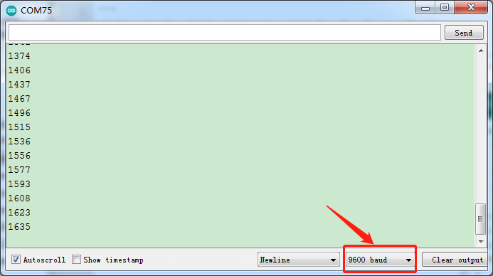
Test Result
Upload the code power up by a USB cable, open the serial monitor and set baud rate to 9600. The higher the temperature, the larger the analog value.
Project 23: Thin-film Pressure Sensor
Overview
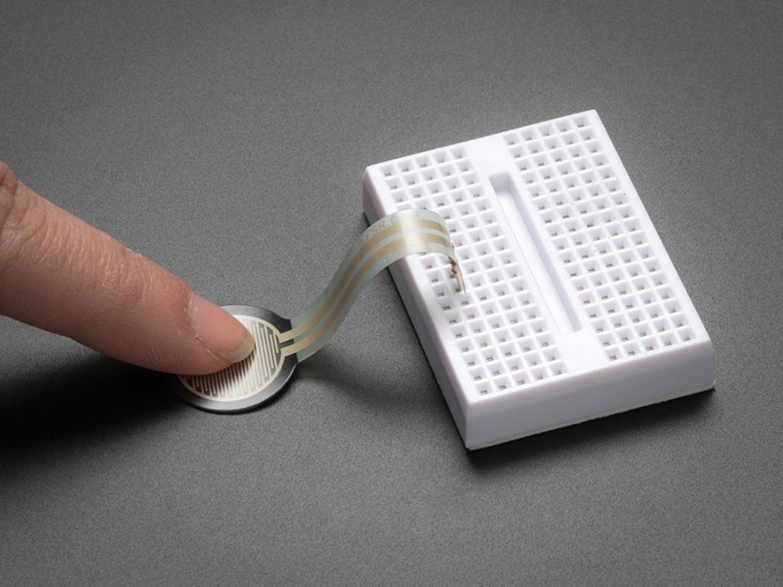
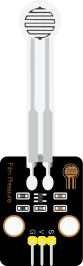
In this kit, there is a Keyestudio thin-film pressure sensor. The thin-film pressure sensor composed of a new type of nano pressure-sensitive material and a comfortable ultra-thin film substrate, has waterproof and pressure-sensitive functions.
In the experiment, we determine the pressure by collecting the analog signal on the S end of the module. The smaller the analog value, the greater the pressure; and the displayed results will shown on the Shell.
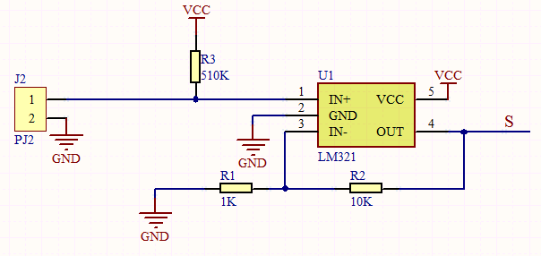
Working Principle
When the sensor is pressed by external forces, the resistance value of sensor will vary. We convert the pressure signals detected by the sensor into the electric signals through a circuit. Then we can obtain the pressure changes by detecting voltage signal changes.
Components
|
|
 |
|
|
| Raspberry Pi Pico Board*1 | Raspberry Pi Pico Shield*1 | Keyestudio Thin-film Pressure Sensor*1 | 3P Dupont Wire*1 | MicroUSB Cable*1 |
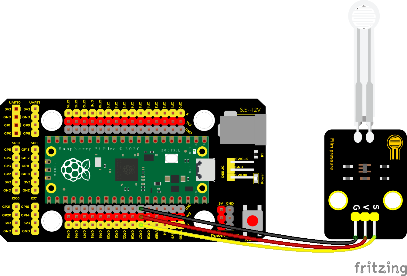
Wiring Diagram
Test Code
/*
* Keyestudio 42 in 1 Starter Kit for Raspberry Pi Pico
* lesson 23
* Film pressure sensor
* http://www.keyestudio.com
*/
int val = 0;
int Film = 27; //the thin-film pressure sensor is connected ADC1
**void setup() **
**void loop() **
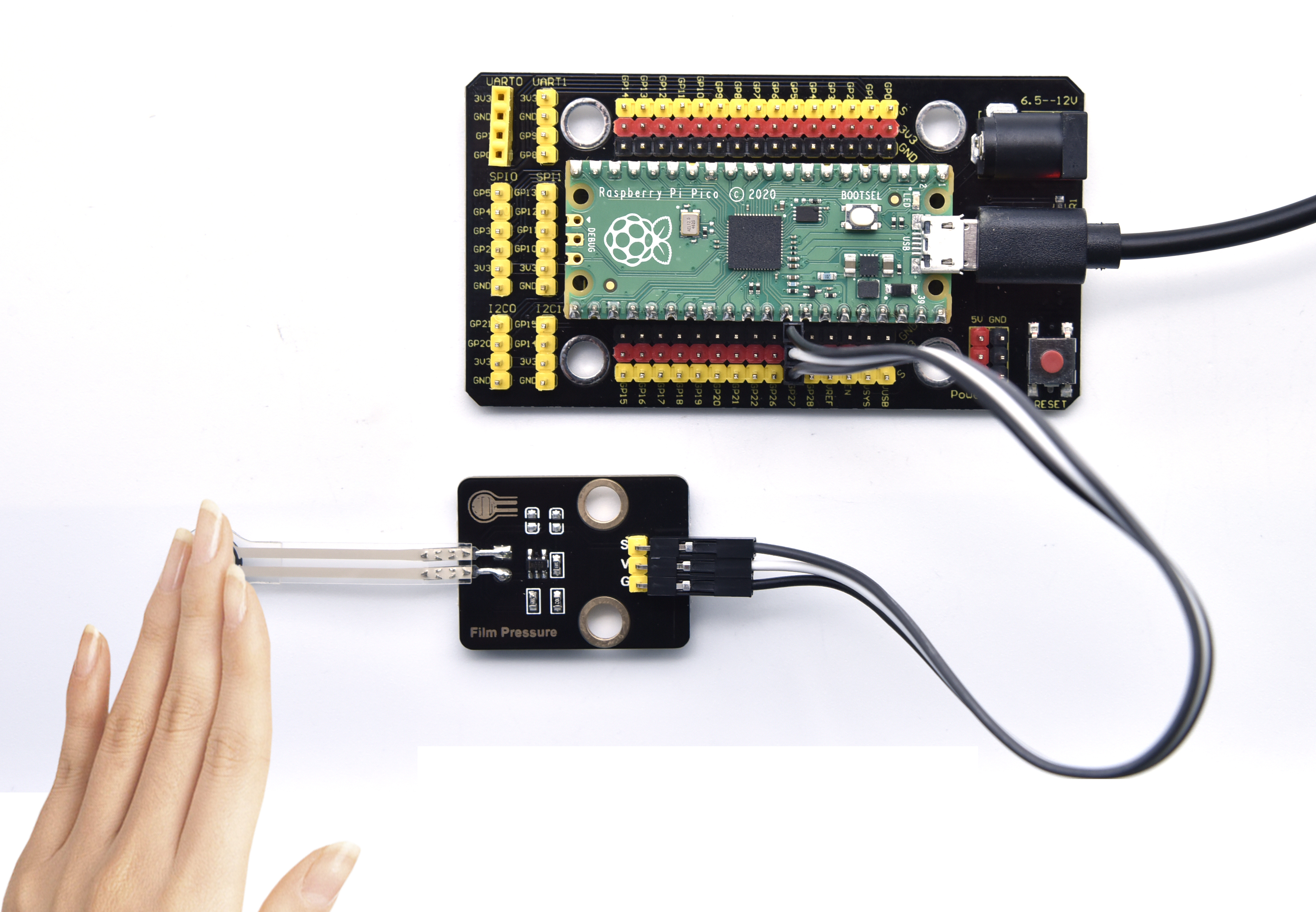
Test Result
Upload the code power up by a USB cable, open the serial monitor and set baud rate to 9600. when the thin-film is pressed by fingers, the analog value will decrease, as shown below;
Project 24: Flame Sensor

Description
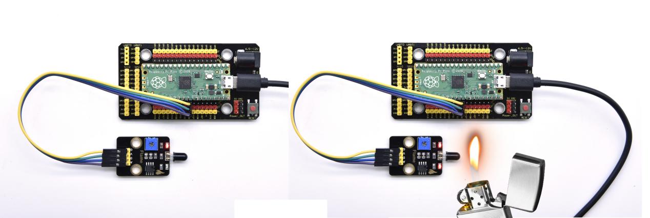
In daily life, it is often seen that a fire broke out without any precaution. It will cause great economic and human loss. So how can we avoid this situation? Right, install a flame sensor and a speaker in those places that easily break out a fire. When the flame sensor detects a fire, the speaker will alarm people quickly to put out the fire.
So in this project, you will learn how to use a flame sensor and an active buzzer module to simulate the fire alarm system.
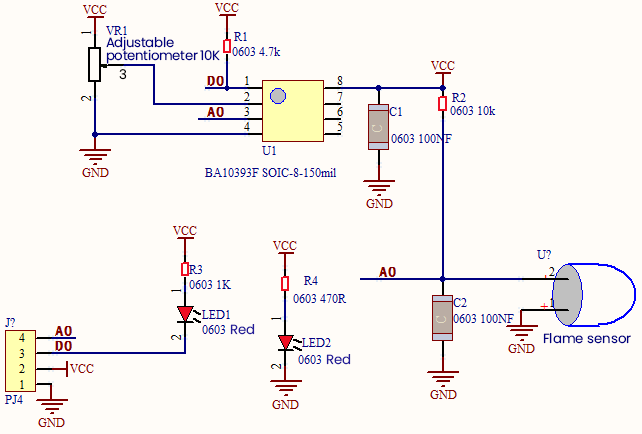
Working Principle
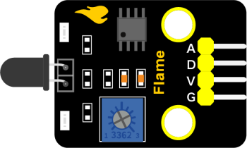
This flame sensor can be used to detect fire or other light sources with wavelength stands at 760nm ~ 1100nm. Its detection angle is about 60°. You can rotate the potentiometer on the sensor to control its sensitivity. Adjust the potentiometer to make the LED at the critical point between on and off state. The sensitivity is the best.
From the below figure, power up. When detecting fire, the digital pin outputs low levels, the red LED2 will light up first, the digital signal terminal D0 outputs a low level, and the red LED1 will light up. The stronger the external infrared light, the smaller the value; the weaker the infrared light, the larger the value.
Components
|
|
 |
|
|
| Raspberry Pi Pico Board*1 | Raspberry Pi Pico Expansion Board*1 | keyestudio DIY Flame Sensor*1 | 4P Dupont Wire*1 | Micro USB Cable*1 |
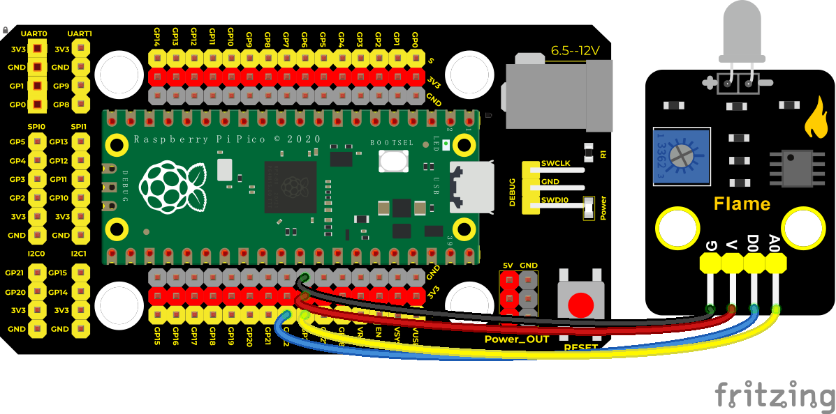
Wiring Diagram
Test Code
/*
* Keyestudio 42 in 1 Starter Kit for Raspberry Pi Pico
* lesson 24
* Flame sensor
* http://www.keyestudio.com
*/
//set pins of the sensor to 22 and 26
int digitalPin = 22;
int analogPin = 26;
//save below variables to the digital signal and analog signal
int analogVal = 0;
int digitalVal = 0;
**void setup() **
**void loop() **
Code Explanation
Two pins we use are defined as 22 and 26 according to the wiring-up diagram, and print digital signals and analog signals respectively.
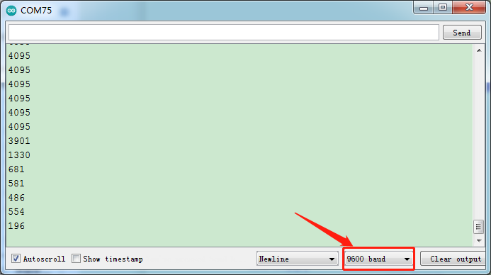
Test Result
Upload the test code and power up,LED2 is on and LED1 is off. Open the monitor and set baud rate to 9600. When fire is detected, LED1 will be on. the digital value will change from 1 to 0, and the analog value will become smaller, as shown in the figure below.
Project 25: MQ-2 Gas Sensor

Description
This analog gas sensor - MQ2 is used in gas leakage detecting equipment in consumer electronics and industrial markets.
This sensor is suitable for detecting LPG, I-butane, propane, methane, alcohol, Hydrogen and smoke. It has high sensitivity and quick response.
In addition, the sensitivity can be adjusted by rotating the potentiometer.
In the experiment, we read the analog value at the A0 port and the D0 port to determine the content of gas.
Working Principle
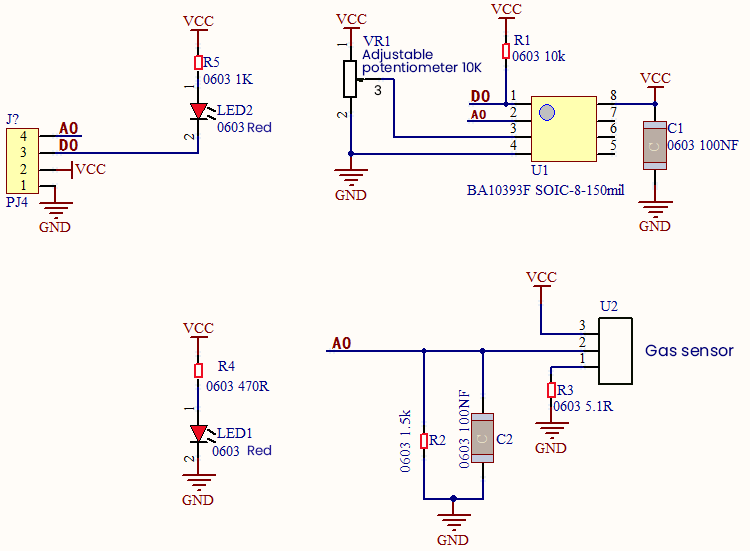
The greater the concentration of smoke, the greater the conductivity, the lower the output resistance, the greater the output analog signal.
When in use, the A0 terminal reads the analog value of the corresponding gas; the D0 terminal is connected to an LM393 chip (voltage comparator), we can adjust the alarm threshold of the measured gas through the potentiometer, and output the digital value at D0. When the measured gas content exceeds the critical point, the D0 terminal outputs a low level; when the measured gas content does not exceed the critical point, the D0 terminal outputs a high level.
Required Components
|
|
|
|
|
| Raspberry Pi Pico Board*1 | Raspberry Pi Pico Expansion Board*1 | keyestudio DIY Analog Gas Sensor*1 | 4P Dupont Wire*1 | Micro USB Cable*1 |
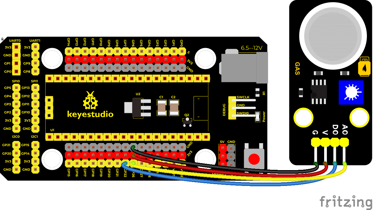
Wiring Diagram
Test Code
/*
* Keyestudio 42 in 1 Starter Kit for Raspberry Pi Pico
* lesson 25
* MQ2
* http://www.keyestudio.com
*/
//connect two pins of the sensor to 22 and 26
int digitalPin = 22;
int analogPin = 26;
//save two variables to digital signals and analog signals
int analogVal = 0;
int digitalVal = 0;
**void setup() **
**void loop() **
**else **
delay(100); //delay in 100ms
}
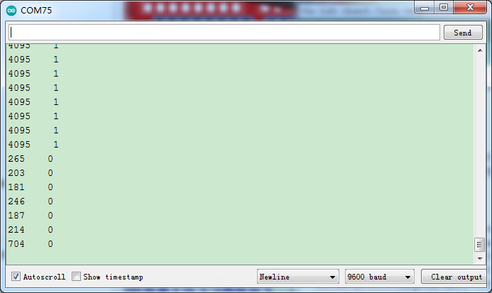
Test Result
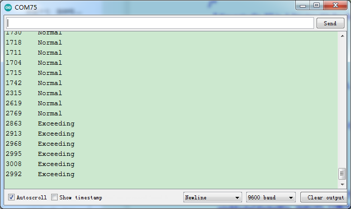
Run the test code, the yellow-green LED on the module lights up, open the serial monitor, set baud rate to 9600 and display the corresponding data and characters.
In the experiment, we can see the simulated value is less than or equal to 2769, the gas content does not exceed the critical point, and the red LED is off; when the simulated value is greater than or equal to 2769, the gas content exceeds the critical point, and the red LED lights up. That means that the analog value of the critical point of gas content is between 2769-2863, we can adjust the critical point by rotating the potentiometer on the sensor.
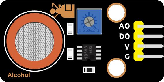
Project 26: MQ-3 Alcohol Sensor
Description
In this kit, there is a MQ-3 alcohol sensor, which uses the gas-sensing material is tin dioxide (SnO2) which has a low conductivity in clean air. When there is alcohol vapor in the environment where the sensor is located, the conductivity of the sensor increases with the increase of the alcohol gas concentration in the air. The change in conductivity can be converted into an output signal corresponding to the gas concentration using a simple circuit.
In the experiment, we read the analog value at the A0 end of the sensor and the digital value at the D0 end to judge the content of alcohol vapor in the air and whether they exceed the standard.
Working Principle
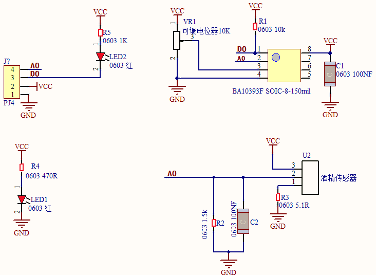
At a certain temperature, the conductivity changes with the composition of the ambient gas. When in use, A0 terminal reads the analog value corresponding to alcohol vapor; D0 terminal is connected to an LM393 chip (comparator), we can adjust and measure the alcohol vapor alarm threshold through the potentiometer, and output the digital value at D0. When the measured alcohol vapor content exceeds the critical point, the D0 terminal outputs a low level; when the measured alcohol vapor content does not exceed the critical point, the D0 terminal outputs a high level.
Components Required
|
|
|
|
|
| Raspberry Pi Pico Board*1 | Raspberry Pi Pico Expansion Board*1 | keyestudio Alcohol Sensor*1 | Dupont Wire4P*1 | Micro USB Cable*1 |
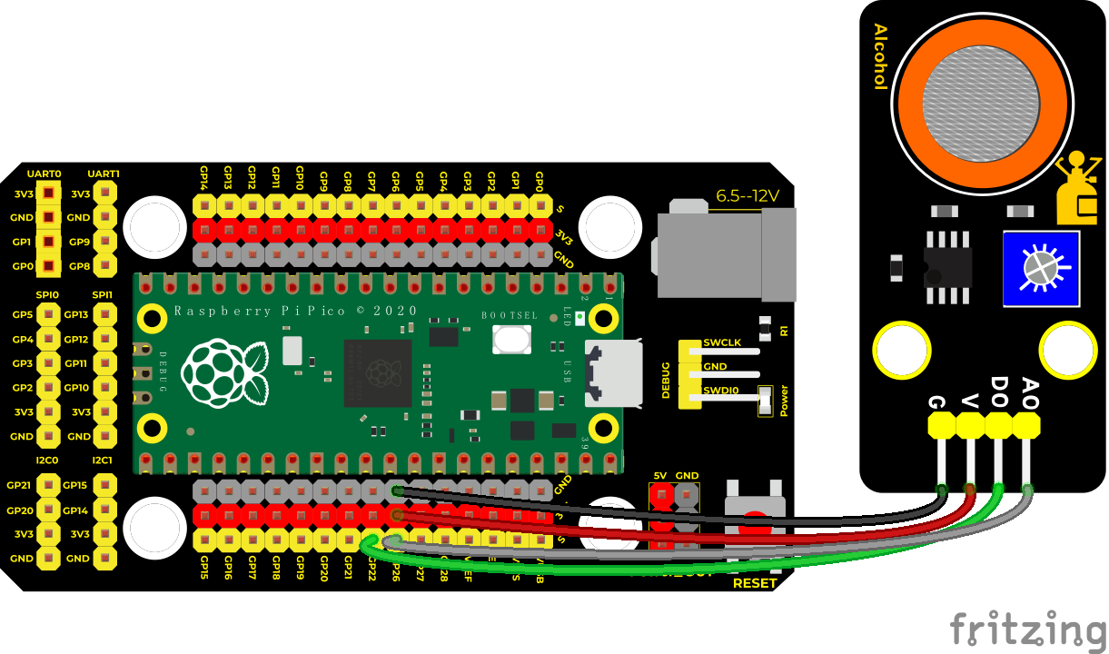
Connection Diagram
Test Code
/*
* Keyestudio 42 in 1 Starter Kit for Raspberry Pi Pico
* lesson 26
* MQ3
* http://www.keyestudio.com
*/
//The two pins of the smoke sensor are connected to 22 and 26 respectively.
int digitalPin = 22;
int analogPin = 26;
//The following two variables store the digital signal and the analog signal respectively int analogVal = 0;
int digitalVal = 0;
**void setup() **
**void loop() **
**else **
delay(100); //delay in 100ms
}
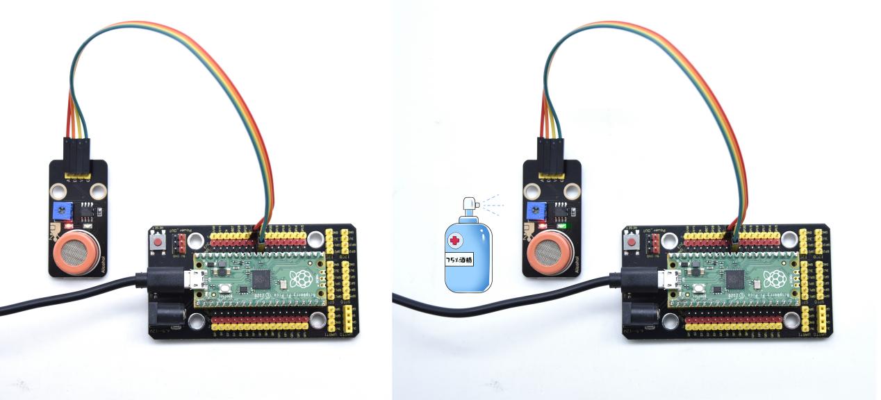
Test Result
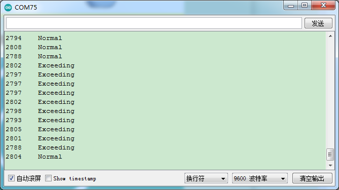
Upload the test code successfully, power up with a USB cable, the red led LED on the module lights up and open the serial monitor and set baud rate to 9600. The serial monitor displays the corresponding data and characters. In the experiment, we can see that when the simulated value of the test is less than or equal to 2788, the gas content does not exceed the critical point, and the yellow-green LED is off; when the simulated value of the test is greater than or equal to 2800, the gas content exceeds the critical point, and the yellow-green LED lights up; then that means that the analog value of the alcohol vapor content critical point is between 2788-2800, we can adjust the critical point by rotating the potentiometer on the sensor.
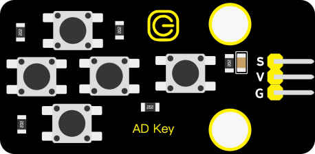
Project 27: Five-key AD Button Module

Description
When we talked about analog and digital sensors earlier, we talked about the single-channel key module. When we press the key, it outputs a low level, and when we release the key, it outputs a high level. We can only read these two digital signals. In fact, the key module ADC acquisition can also be performed. In this kit, a DIY electronic building block five-way AD button module is included.
We can judge which key is pressed through the analog value. In the experiment, we print out the key press information in the shell.
Working Principle
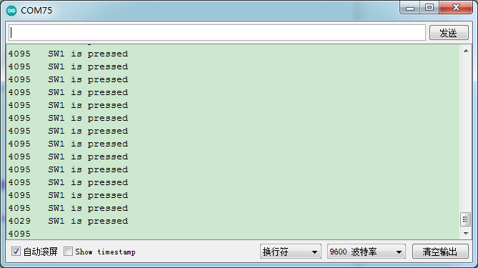
Let’s look at the schematic diagram, when we do not press the key, the OUT of S output to the signal end is pulled down by R1. At this time, we read the low level 0V. When we press the key SW1, the OUT of the output to the signal end S is directly connected to the VCC. At this time, we read the high level 3.3V(the figure is marked as a 10-bit ADC(0~1023) and VCC is 5V. The principle is the same. Here we have VCC of 3.3V and ADC mapped to 16 bits), which is an analog value of 65535.
Next,when we press the key SW2, the OUT terminal voltage of the signal we read is the voltage between R2 and R1, namely VCC*R1/(R2+R1), which is about 2.64V, and the analog value is about 52219.
When we press the key SW3, the OUT terminal voltage of the signal we read is the voltage between R2+R3 and R1, namely VCC*R1/(R3+R2+R1), which is about 1.99V, and the analog value is about 39360.
When we press the key SW4, the OUT terminal voltage of the signal we read is the voltage between R2+R3+R4 and R1, namely VCC*R1/(R4+R3+R2+R1), about 1.31V, and the analog value is about 26109.
Similarly, when we press the key SW5, the OUT terminal voltage of the signal we read is the voltage between R2+R3+R4+R5 and R1, namely VCC*R1/(R5+R4+R3+R2+R1), which is about 0.68V, and the analog value is about 13415.
Components Required
|
|
 |
|
|
| Raspberry Pi Pico Board*1 | Raspberry Pi Pico Expansion Board*1 | keyestudio 5-Channel AD Button Module*1 | 3P Dupont Wire*1 | Micro USB Cable*1 |
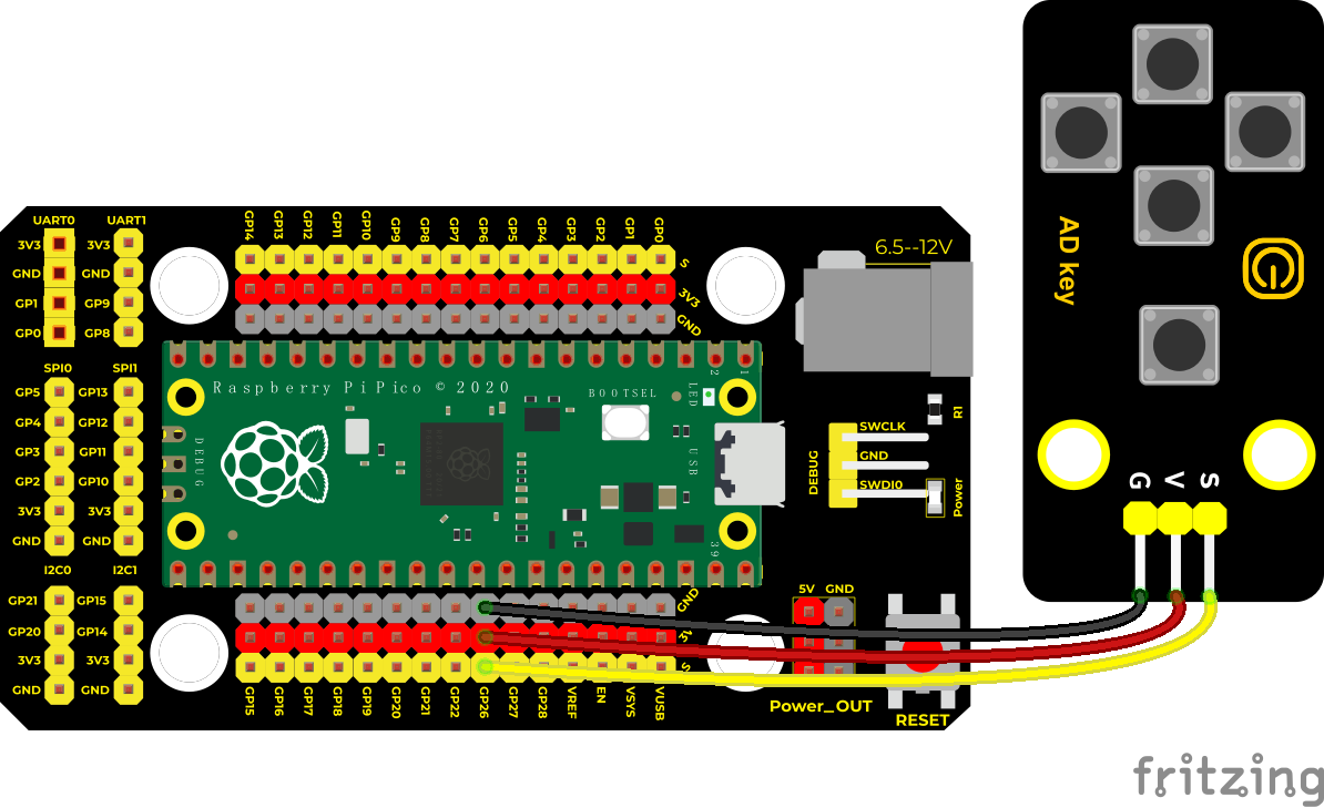
Wiring Diagram
Test Code
/*
* Keyestudio 42 in 1 Starter Kit for Raspberry Pi Pico
* lesson 27
* AD Key
* http://www.keyestudio.com
*/
int val = 0;
int ADkey = 26; //Define five AD buttons to connect to GPIO26
**void setup() **
**void loop() else if (val <= 1200) else if (val <= 2000) else if (val <= 2800) else if (val <= 3500) else **
}
Code Explanation
We assign the read analog value to the variable val, and the serial monitor displays the value of val, (we set to 9600).
When the analog value is in the range of 500 and 1200, the button SW5 is pressed; when the analog value is in the 1200 and 2000, the button SW4 is pressed; when the analog value is between 2000 and 2800, the button SW3 is pressed; when the analog value is between 2800 and 3500, the button SW2 is pressed. Press; When the analog value is above 3500, we judge that the button SW1 is pressed.
Test Result
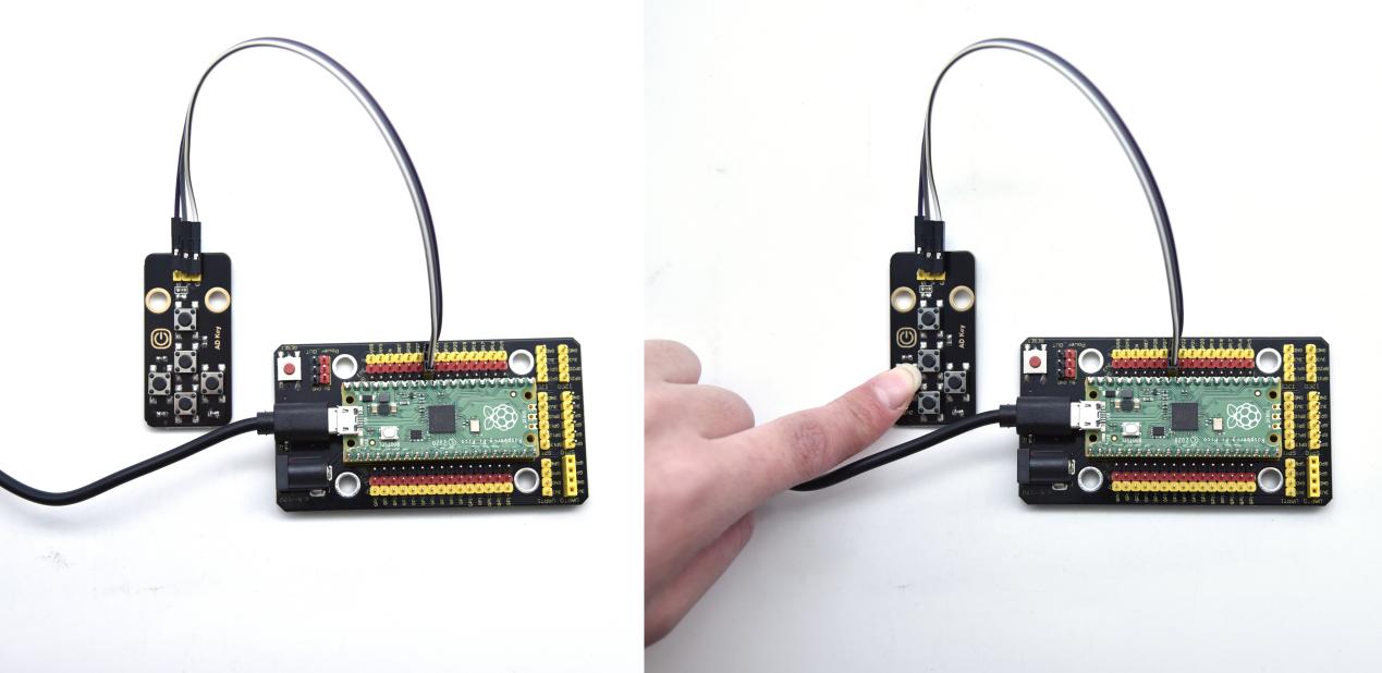
After uploading the test code successfully, power on, open the serial monitor and set baud rate to 9600; when the button is pressed, the serial monitor prints out the corresponding information, as shown in the figure below.
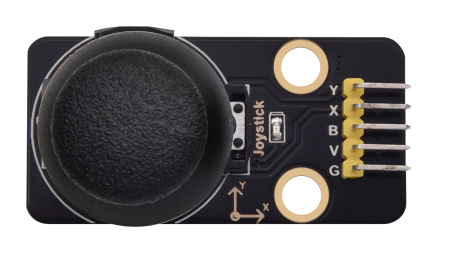
Project 28: Joystick Module

Overview
Game handle controllers are ubiquitous.
It mainly uses PS2 joysticks. When controlling it, we need to connect the X and Y ports of the module to the analog port of the single-chip microcomputer, port B to the digital port of the single-chip microcomputer, VCC to the power output port(3.3-5V), and GND to the GND of the MCU. We can read the high and low levels of two analog values and one digital port) to determine the working status of the joystick on the module.
In the experiment, two analog values(x axis and y axis) will be shown on Shell.
Working Principle
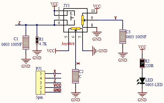
In fact, its working principle is very simple. Its inside structure is equivalent to two adjustable potentiometers and a button. When this button is not pressed and the module is pulled down by R1, low levels will be output ; on the contrary, when the button is pressed, VCC will be connected (high levels), When we move the joystick, the internal potentiometer will adjust to output different voltages, and we can read the analog value.
Components
|
|
 |
|
|
| Raspberry Pi Pico Board*1 | Raspberry Pi Pico Shield*1 | Keyestudio Joystick Module*1 | 5P Dupont Wire*1 | Micro USB Cable*1 |
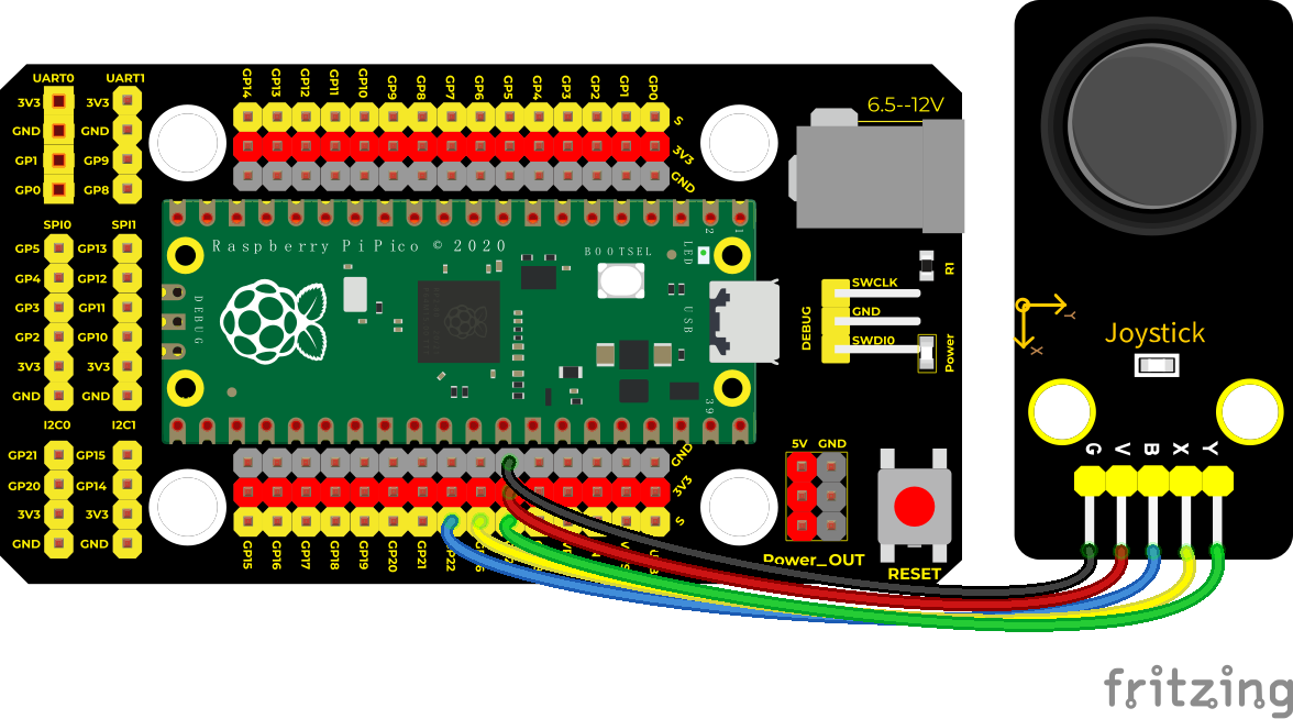
Wiring Diagram
Test Code
/*
* Keyestudio 42 in 1 Starter Kit for Raspberry Pi Pico
* lesson 28
* Joystick
* http://www.keyestudio.com
*/
int X = 0;
int Y = 0;
int Button = 0;
**void setup() **
**void loop() **
Code Explanation
In the experiment, according to the wiring diagram, the x pin is set to GP26, the y pin is set to GP27 and the pin of the joystick is set to GP22. Teen the serial monitor displays the test data.
Test Result
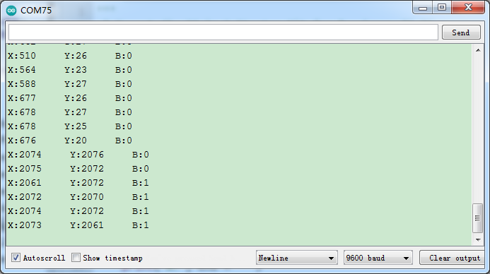
Upload the code power up by a USB cable, open the serial monitor and set baud rate to 9600.
The serial monitor will show the corresponding value. Move the joystick, the analog value of X axis and Y axis will change. Press the button, the digital value is 1, on the contrary is 0. as shown below;
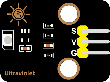
Project 29: Ultraviolet Sensor

Description
There is a ultraviolet Sensor used for UV index monitoring, UV radiation dose measurement, flame detection. Suitable for measuring UV index of smart wearable devices, such as UV index detection of watches, smartphones and outdoor equipment. It can also be used to monitor the intensity of UV light, or as a UV flame detector when UV sanitizing items. The sensor has a specific spectral response. In the experiment, we use the purple led module to test the UV module, and then display the results on the shell.
Working Principle
The output current of the UV sensor is proportional to the light intensity, and the output of the product has a very high consistency. The module circuit has been set up, and we directly use the ADC to collect the analog signal.
Required Components
|
|
|
|
|
|
| Raspberry Pi Pico Board*1 | Raspberry Pi Pico Expansion Board*1 | Keyestudio Ultraviolet Sensor*1 | 3P Dupont Wire*2 | Micro USB Cable*1 | Keyestudio DIY Purple LED*1 |
Wiring Diagram
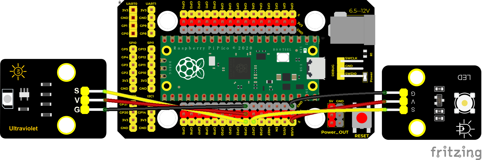
(V of led module is connected to VUSB(5V) to make the LED brighter)
Test Code
/*
* Keyestudio 42 in 1 Starter Kit for Raspberry Pi Pico
* lesson 29
* UV sensor
* http://www.keyestudio.com
*/
int val = 0;
int led = 27;
**void setup() **
**void loop() **
Code Explanation
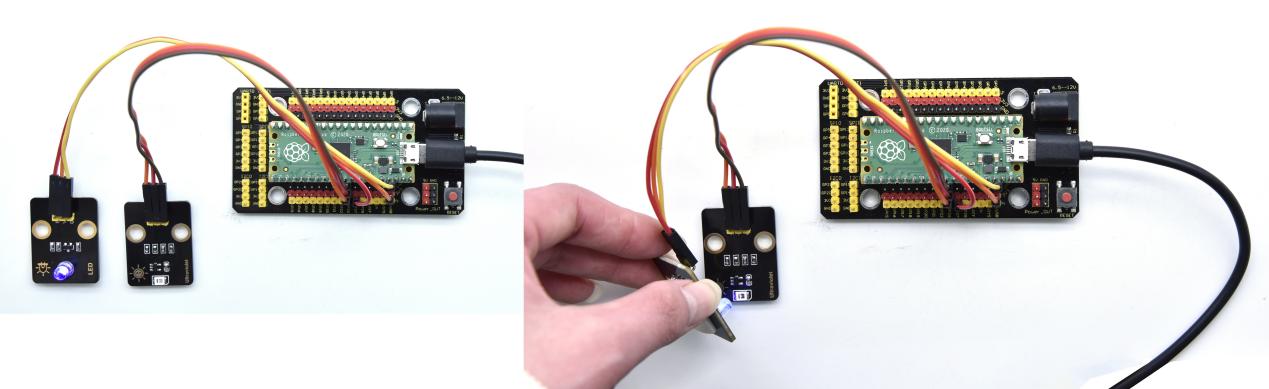
We first light up the purple LED, and then use it to illuminate the UV module to see the changes in the data on the serial monitor.
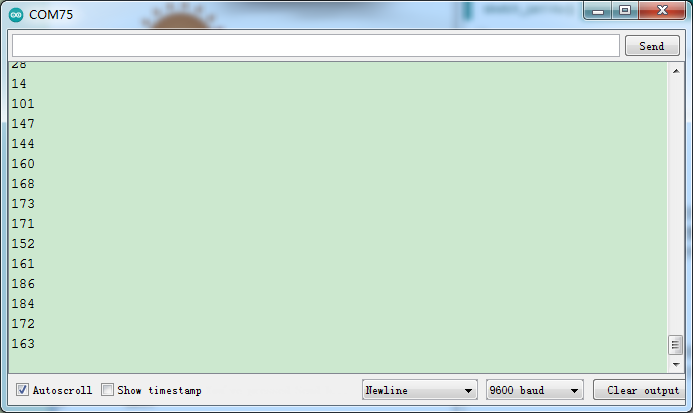
Test Result
Upload the test code, open the serial monitor and set baud rate to 9600. When we make the purple LED close to the ultraviolet module, view the data on the monitor, as shown below:
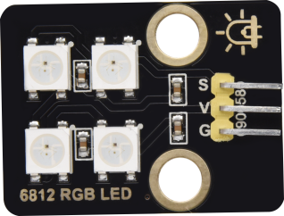
Project 30: SK6812 RGB Module

Overview
In previous lessons, we learned about the plug-in RGB module and used PWM signals to color the three pins of the module.
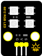
There is a Keyestudio 6812 RGB module whose the driving principle is different from the plug-in RGB module. It can only control with one pin. This is a set. It is an intelligent externally controlled LED light source with the control circuit and the light-emitting circuit. Each LED element is the same as a 5050 LED lamp bead, and each component is a pixel. There are four lamp beads on the module, which indicates four pixels
In the experiment, we make different lights show different colors.
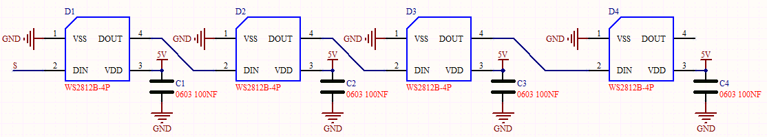
Working Principle
From the schematic diagram, we can see that these four pixel lighting beads are all connected in series. In fact, no matter how many they are, we can use a pin to control a light and let it display any color. The pixel point contains a data latch signal shaping amplifier drive circuit, a high-precision internal oscillator and a 12V high-voltage programmable constant current control part, which effectively ensures the color of the pixel point light is highly consistent.
The data protocol adopts a single-wire zero-code communication method. After the pixel is powered up and reset, the S terminal receives the data transmitted from the controller. The first 24bit data sent is extracted by the first pixel and sent to the data latch of the pixel.
Components
|
|
 |
|
|
| Raspberry Pi Pico Board*1 | Raspberry Pi Pico Shield*1 | Keyestudio 6812 RGB Module*1 | 3P Dupont Wire*1 | MicroUSB Cable*1 |
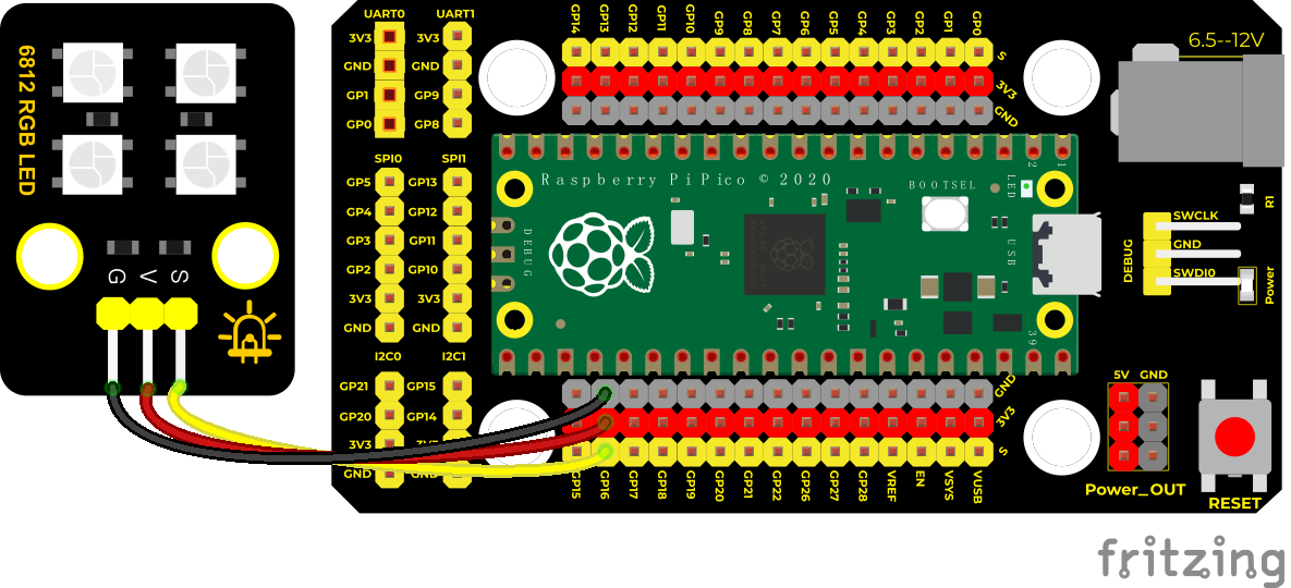
Wiring Diagram
Test Code
/*
* Keyestudio 42 in 1 Starter Kit for Raspberry Pi Pico
* lesson 30
* 6812 RGB LED
* http://www.keyestudio.com
*/
#include”rgb.h”
RGB rgb(16,4); //rgb(pin, num); num = 0-100
///////////////////////////////////////////////////////////////////////////////////
**void setup() **
///////////////////////////////////////////////////////////////////////////////////
**void loop() **
}
Code Explanation
We use the library function . You can refer to
project Add libraries.
. You can refer to
project Add libraries.
Interfaces and functions:
RGB rgb(16,4); used to initialize 6812RGB,16 is the pin number,4 means the number of light beads
rgb.setBrightness(100); used to set the brightness(0-255) of the 6812RGB module. The larger the brightness value, the brighter light beads. 255 means the brightest.
rgb.clear(); used to clear up the screen
rgb.setPixelColor(uint16_t n, uint8_t r, uint8_t g, uint8_t b); this function is used to set locations of light beads of the 6812RGB module.
rgb.show(); used to display 6812RGB,necessary, if without this sentence, light beads can’t refresh.
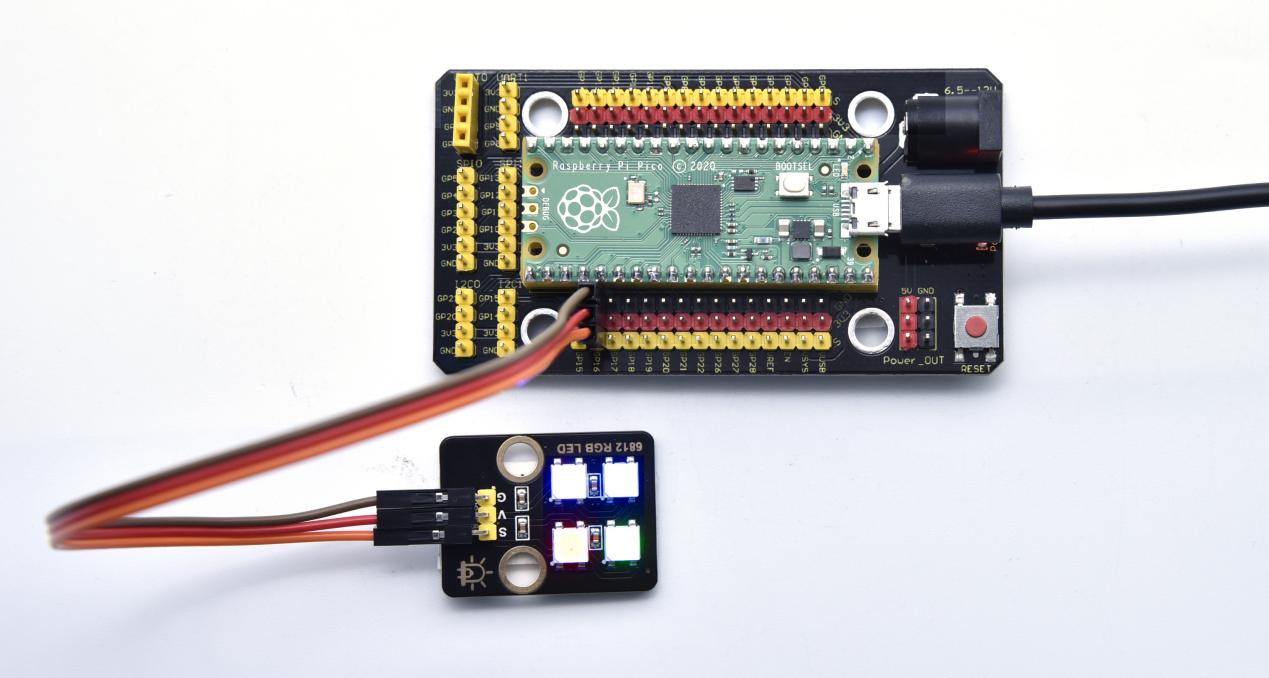
Test Result
Upload the test code, wire up and power up. Then we can the module display red, green, blue and white color.
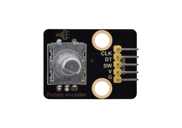
Project 31: Rotary Encoder
Overview
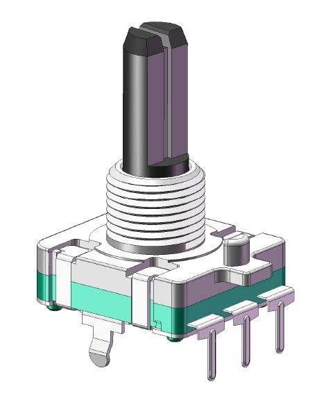
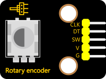
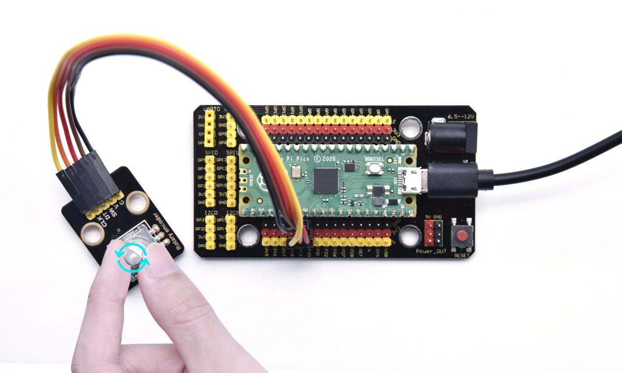
In this kit, there is a Keyestudio rotary encoder, dubbed as switch encoder. It is applied to automotive electronics, multimedia audio, instrumentation, household appliances, smart home, medical equipment and so on.
In the experiment, it it used for counting. When we rotate the rotary encoder clockwise, the set data falls by 1; if you rotate it anticlockwise, the set data is up 1; and when the middle button is pressed, the value will be show on Shell.
Working Principle
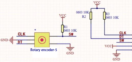
The incremental encoder converts the displacement into a periodic electric signal, and then converts this signal into a counting pulse, and the number of pulses indicates the size of the displacement.This module mainly uses 20-pulse rotary encoder components. It can calculate the number of pulses output during clockwise and reverse rotation. There is no limit to count rotation. It resets to the initial state, that is, starts counting from 0.
Components
|
|
 |
|
|
| Raspberry Pi Pico Board*1 | Raspberry Pi Pico Shield*1 | Keyestudio Rotary Encoder*1 | 5P Dupont Wire*1 | MicroUSB Cable*1 |
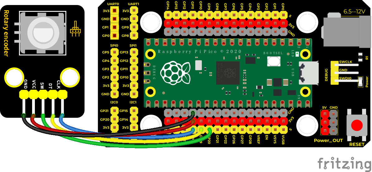
Wiring Diagram
Test Code
/*
Keyestudio 42 in 1 Starter Kit for Raspberry Pi Pico
lesson 31
Encoder
http://www.keyestudio.com
*/
//Interfacing Rotary Encoder with Arduino
//Encoder Switch -> pin 20
//Encoder DT -> pin 19
//Encoder CLK -> pin 18
int Encoder_DT = 19;
int Encoder_CLK = 18;
int Encoder_Switch = 20;
int Previous_Output;
int Encoder_Count;
**void setup() **
**void loop() **
else
}
Previous_Output = digitalRead(Encoder_DT);
if (digitalRead(Encoder_Switch) == 0)
}
}
Code Explanation
Set CLK to GP18 and DAT to GP19
This code is set well in the library file. When CLK descends, read the voltage of DAT, when DAT is a HIGH level, the value of the rotary encoder is added by 1; when DAT is a LOW level, the value of the rotary encoder is cut down 1.
Set the pin of the button(GP20) to LOW ans print.
Test Result
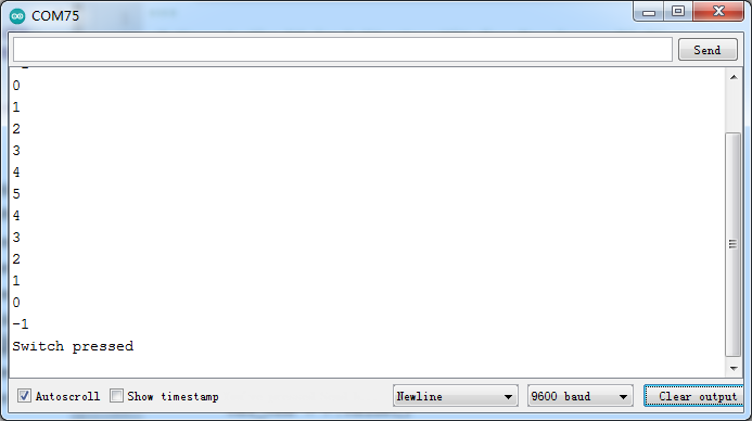
Upload the code power up by a USB cable, open the serial monitor and set baud rate to 9600. Rotate the knob on the rotary encoder clockwise, the displayed data will decrease; on the contrary, in anticlockwise way, the data will rise. Equally, press the button on the rotary encoder,“Switch pressed”will be shown.
Project 32: Servo Control

Overview
Servo motor is a position control rotary actuator. It mainly consists of a housing, a circuit board, a core-less motor, a gear and a position sensor. Its working principle is that the servo receives the signal sent by MCU or receiver and produces a reference signal with a period of 20ms and width of 1.5ms, then compares the acquired DC bias voltage to the voltage of the potentiometer and obtain the voltage difference output.
In general, servo has three lines in brown, red and orange. The brown wire is grounded, the red one is a positive pole line and the orange one is a signal line.
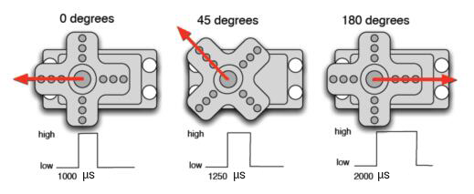
Working Principle
When the motor speed is constant, the potentiometer is driven to rotate through the cascade reduction gear, which leads that the voltage difference is 0, and the motor stops rotating. Generally, the angle range of servo rotation is 0° –180 °
The rotation angle of servo motor is controlled by regulating the duty cycle of PWM (Pulse-Width Modulation) signal. The standard cycle of PWM signal is 20ms (50Hz). Theoretically, the width is distributed between 1ms-2ms, but in fact, it’s between 0.5ms-2.5ms. The width corresponds the rotation angle from 0° to 180°. But note that for different brand motors, the same signal may have different rotation angles.

Components
|
|
 |
|
| Raspberry Pi Pico Board*1 | Raspberry Pi Pico Shield*1 | Servo*1 | Micro USB Cable*1 |
Wiring Diagram
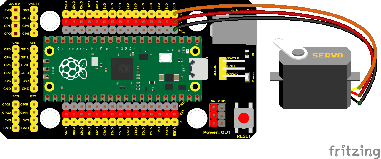
Test Code
//Code 1:
/*
Keyestudio 42 in 1 Starter Kit for Raspberry Pi Pico
lesson 32.1
servo_1
http://www.keyestudio.com
*/
int servoPin = 0;//Pins of the servo
**void setup() **
**void loop() **
**void servopulse(int pin, int myangle) **
}
Code 2:
/*
Keyestudio 37 in 1 Starter Kit for Raspberry Pi Pico
lesson 29.2
servo_2
http://www.keyestudio.com
*/
#include <Servo.h> //servo library
Servo myservo;
**void setup() **
**void loop() **
**for (int pos = 180; pos > 0; pos–) **
delay(2000);//wait for 2s
}
Code Explanation
Code 1:
map(value, fromLow, fromHigh, toLow, toHigh);
Value is the value we map. fromLow, fromHigh is the maximum and minimum value;
toLow, toHigh are the upper limit and lower limit we map. For example, map(myangle, 0, 180, 500, 2500) means that an angle value myangle (0°-180°)the mapping range is from 500us to 2500us.
We use the function servopulse() to make the servo move. We also make the servo rotate 0°, 90°and 180°cyclically.
Code 2:
The library of the servo
 has been
downloaded,click
has been
downloaded,click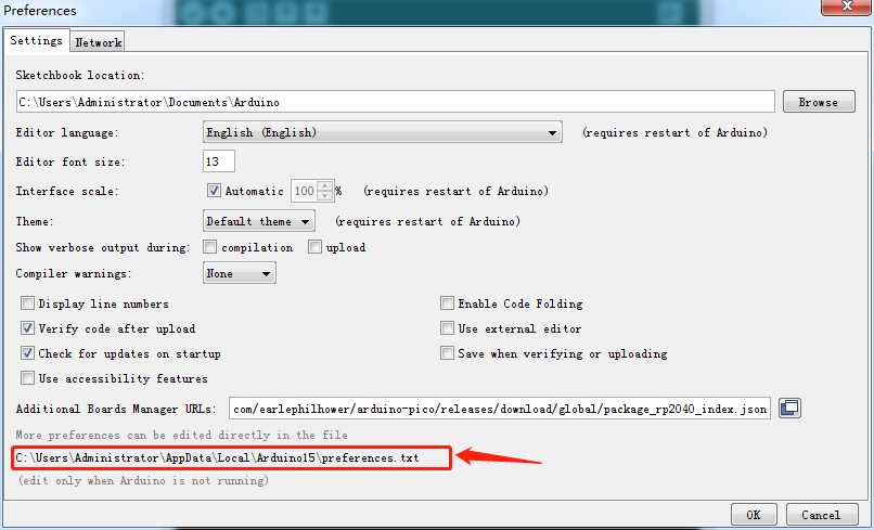 to
find the path
to
find the path
The you can get the library of the servo.
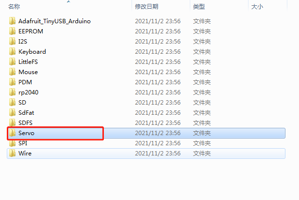 。
。myservo.write(pos): angle values of the servo. myservo.read(): read angle values of the servo.
Test Result
Upload the code1 and power up,the servo will rotate 0°,90° and 180°.
Upload the code 2 and power up, the servo will rotate from 0° to 180° by moving 1° for each 15ms.
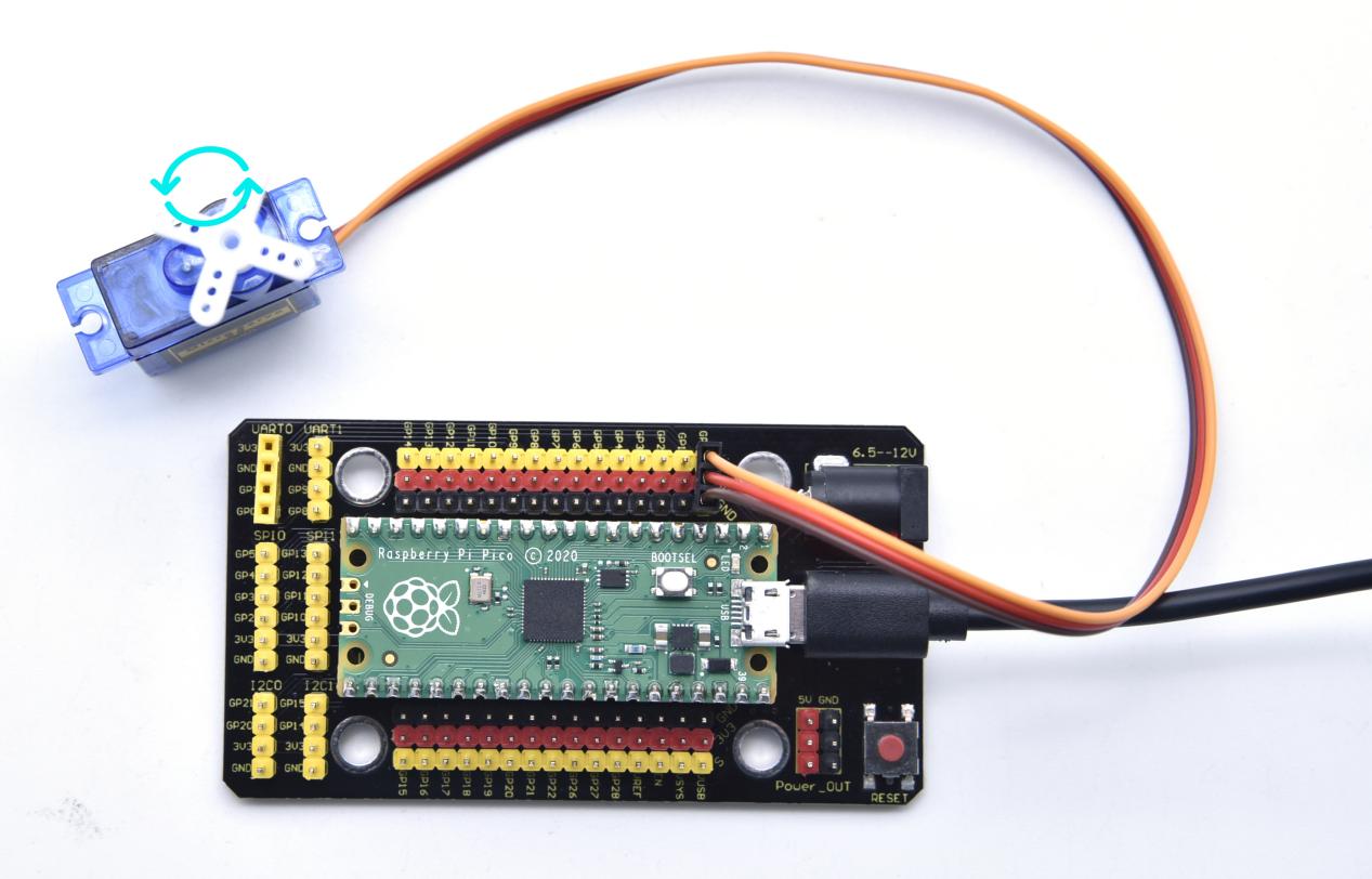
Project 33: Ultrasonic Sensor
Overview
In this kit, there is a keyes HC-SR04 ultrasonic sensor, which can detect obstacles in front and the detailed distance between the sensor and the obstacle. Its principle is the same as that of bat flying. It can emit the ultrasonic signals that cannot be heard by humans. When these signals hit an obstacle and come back immediately. The distance between the sensor and the obstacle can be calculated by the time gap of emitting signals and receiving signals.
In the experiment, we use the sensor to detect the distance between the sensor and the obstacle, and print the test result.
Ultrasonic detector module can provide 2cm-450cm non-contact sensing distance, and its ranging accuracy is up to 3mm, very good to meet the normal requirements. The module includes an ultrasonic transmitter and receiver as well as the corresponding control circuit.
Working Principle
The most common ultrasonic ranging method is the echo detection. As shown below; when the ultrasonic emitter emits the ultrasonic waves towards certain direction, the counter will count. The ultrasonic waves travel and reflect back once encountering the obstacle. Then the counter will stop counting when the receiver receives the ultrasonic waves coming back.
The ultrasonic wave is also sound wave, and its speed of sound V is related to temperature. Generally, it travels 340m/s in the air. According to time t, we can calculate the distance s from the emitting spot to the obstacle.
s=340t/2.
The HC-SR04 ultrasonic ranging module can provide a non-contact distance sensing function of 2cm-400cm, and the ranging accuracy can reach as high as 3mm; the module includes an ultrasonic transmitter, receiver and control circuit. Basic working principle:
1. First pull down the TRIG, and then trigger it with at least 10us high level signal;
2. After triggering, the module will automatically transmit eight 40KHZ square waves, and automatically detect whether there is a signal to return.
3. If there is a signal returned back, through the ECHO to output a high level, the duration time of high level is actually the time from emission to reception of ultrasonic.
Test distance = high level duration * 340m/s * 0.5.
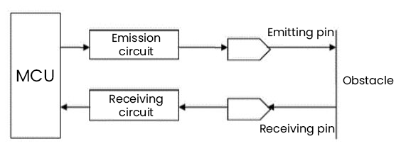
Components
|
|
 |
|
|
| Raspberry Pi Pico Board*1 | Raspberry Pi Pico Shield*1 | keyestudio SR01 Ultrasonic Sensor*1 | 4P Dupont Wire*1 | Micro USB Cable*1 |
Connection Diagram
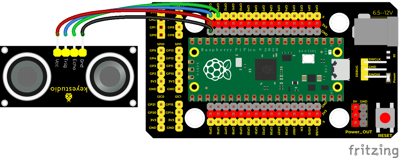
Test Code/*
Keyestudio 42 in 1 Starter Kit for Raspberry Pi Pico
lesson 33
Ultrasonic
http://www.keyestudio.com
*/
int distance = 0; //Define a variable to receive the distance
int EchoPin = 13; //Echo is connected to GP13
int TrigPin = 14; //Trig is connected to GP14
**float checkdistance() **
**void setup() **
**void loop() **
**else **
}
Code Explanation
The maximum test distance of HC-SR04 ultrasonic sensor is 3-4m, and the minimum test distance is 2cm. Setting code When the detection distance is less than 2cm or greater than or equal to 400cm, the serial monitor will display -1. We display the distance between the sensor and the obstacle on the serial monitor.
Test Result
Upload the code power up by a USB cable, open the serial monitor and set baud rate to 9600.
If the obstacle is beyond the detection range, the monitor will show “-1”; on the contrary, the monitor will display the distance away from the obstacle.
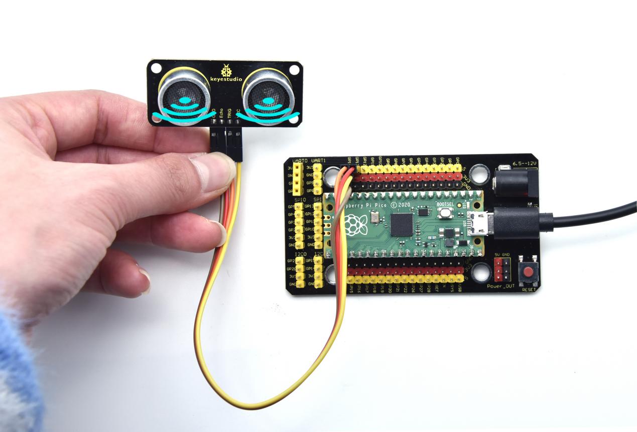
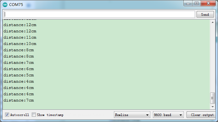
Project 34: IR Receiver Module

Overview
There is no doubt that infrared remote control is ubiquitous in daily life. It is used to control various household appliances, such as TVs, stereos, video recorders and satellite signal receivers. Infrared remote control is composed of infrared transmitting and infrared receiving systems, that is, an infrared remote control and infrared receiving module and a single-chip microcomputer capable of decoding.
In this experiment, we need to know how to use the infrared receiving sensor. The infrared receiving sensor mainly uses the VS1838B infrared receiving sensor element. It integrates receiving, amplifying, and demodulating. The internal IC has already completed the demodulation, and the output is a digital signal. It can receive 38KHz modulated remote control signal. In the experiment, we use the IR receiver to receive the infrared signal emitted by the external infrared transmitting device, and display the received signal in the shell.
Working Principle
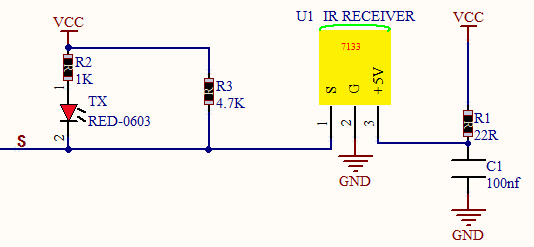
The main part of the IR remote control system is modulation, transmission and reception. The modulated carrier frequency is generally between 30khz and 60khz, and most of them use a square wave of 38kHz and a duty ratio of 1/3. A 4.7K pull-up resistor R3 is added to the signal end of the infrared receiver.
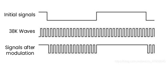
Components
|
|
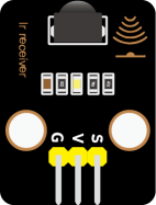 |
|
|
 |
| Raspberry Pi Pico Board*1 | Raspberry Pi Pico Shield*1 | Keyestudio DIY IR Receiver *1 |
3P Dupont Wire*1 | Micro USB Cable*1 |
Remote Control*1 |
Wiring Diagram
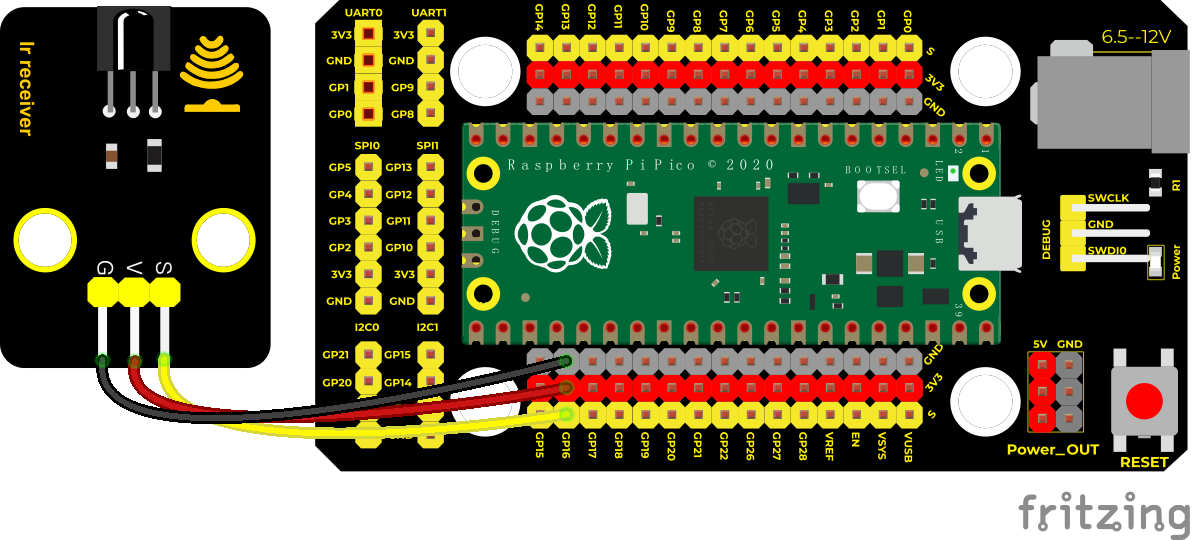
Test Code
/*
Keyestudio 42 in 1 Starter Kit for Raspberry Pi Pico
lesson 34
IR Receiver
http://www.keyestudio.com
*/
#include”ir.h”
IR IRreceive(16);
////////////////////
**void setup() **
////////////////////
**void loop() **
}
Code Explanation
We need to import the library .
.
Key values are shown below;
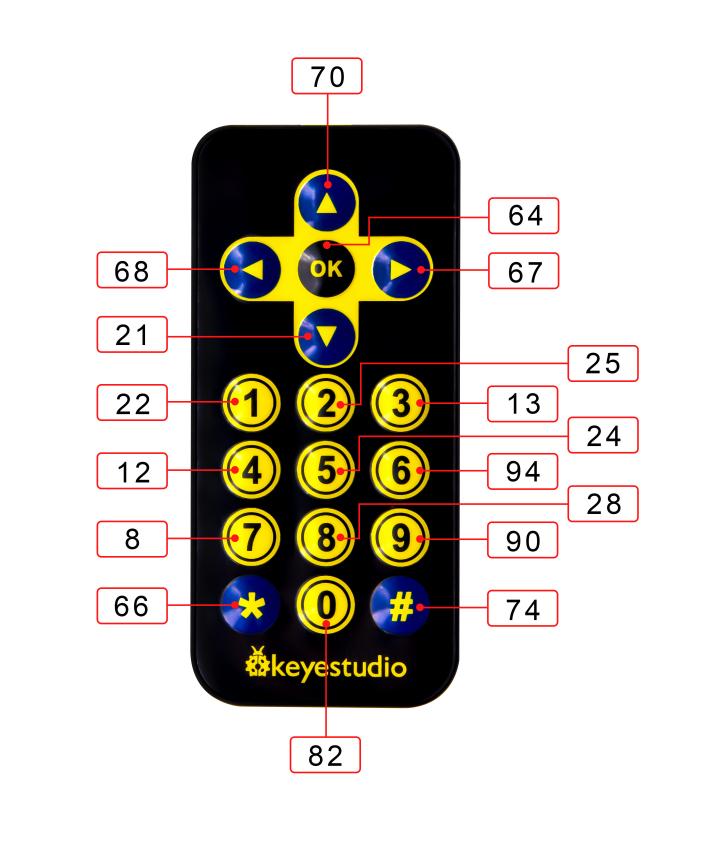
Test Result
Wire up, upload the code, power up and open serial monitor. Point at the IR receiver and press keys on the IR remote control. Then the lED on the IR receiver will flash, as shown below;
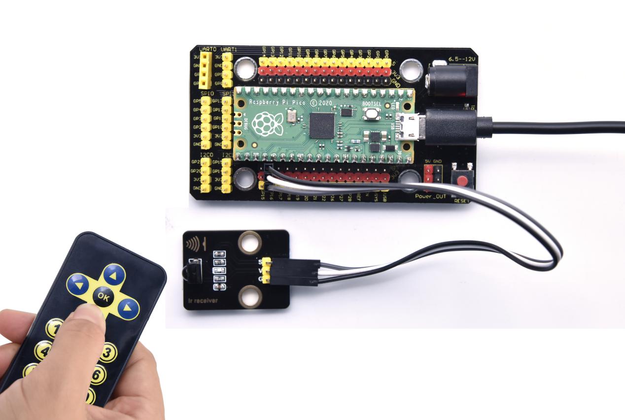
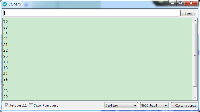
Project 35: DS18B20 Temperature Sensor

Description
The DS18B20 is a 1-wire programmable Temperature sensor from maxim integrated. It is widely used to measure temperature in hard environments like in chemical solutions, mines or soil etc. The constriction of the sensor is rugged and also can be purchased with a waterproof option making the mounting process easy. It can measure a wide range of temperature from -55°C to +125° with a decent accuracy of ±5°C. Each sensor has a unique address and requires only one pin of the MCU to transfer data so it a very good choice for measuring temperature at multiple points without compromising much of your digital pins on the microcontroller.
Working Principle
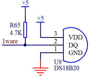
The hardware interface of the 1-Wire bus is very simple, just connect the data pin of the DS18B20 to an IO port of the microcontroller. The timing of the 1-Wire bus is relatively complex. Many students can’t understand the timing diagram independently here. We have encapsulated the complex timing operations in the library, and you can use the library functions directly.
Schematic Diagram of DS18B20
This can save up to 12-bit temperature vale. In the register, save in code complement. As shown below;
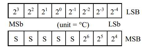
A total of 2 bytes, LSB is the low byte, MSB is the high byte, where MSb is the high byte of the byte, LSb is the low byte of the byte. As you can see, the binary number, the meaning of the temperature represented by each bit, is expressed. Among them, S represents the sign bit, and the lower 11 bits are all powers of 2, which are used to represent the final temperature. The temperature measurement range of DS18B20 is from -55 degrees to +125 degrees, and the expression form of temperature data, S represents positive and negative temperature, and the resolution is 2﹣⒋, which is 0.0625.
Required Components
|
|
|
|
|
| Raspberry Pi Pico Board*1 | Raspberry Pi Pico Expansion Board*1 | Keyestudio DIY 18B20 Temperature Sensor*1 | 3P Dupont Wire*1 | Micro USB Cable*1 |
Wiring Diagram
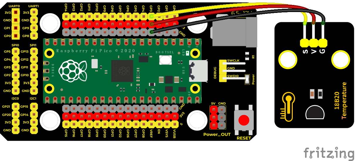
Test Code
/*
* Keyestudio 42 in 1 Starter Kit for Raspberry Pi Pico
* lesson 35
* ds18b20
* http://www.keyestudio.com
*/
#include <DS18B20.h>
//ds18b20 pin to 3
DS18B20 ds18b20(3);
**void setup() **
**void loop() **
Code Explanation1.
We need to import the DS18B20 module.
Set the pin to 3.
Set a double decimal variable to temp, and assign the measured result to temp.
The serial monitor displays the temp value, and the baud rate needs to be set before displaying (our default setting is 9600, which can be changed).
We add the unit behind the data. If the unit is directly set to °C, the test result will be garbled. So we directly replace ℃ with C.
Test Result
Run the test code, power on, open the serial monitor and set baud rate to 9600. The monitor will display the temperature of the current environment, as shown below.
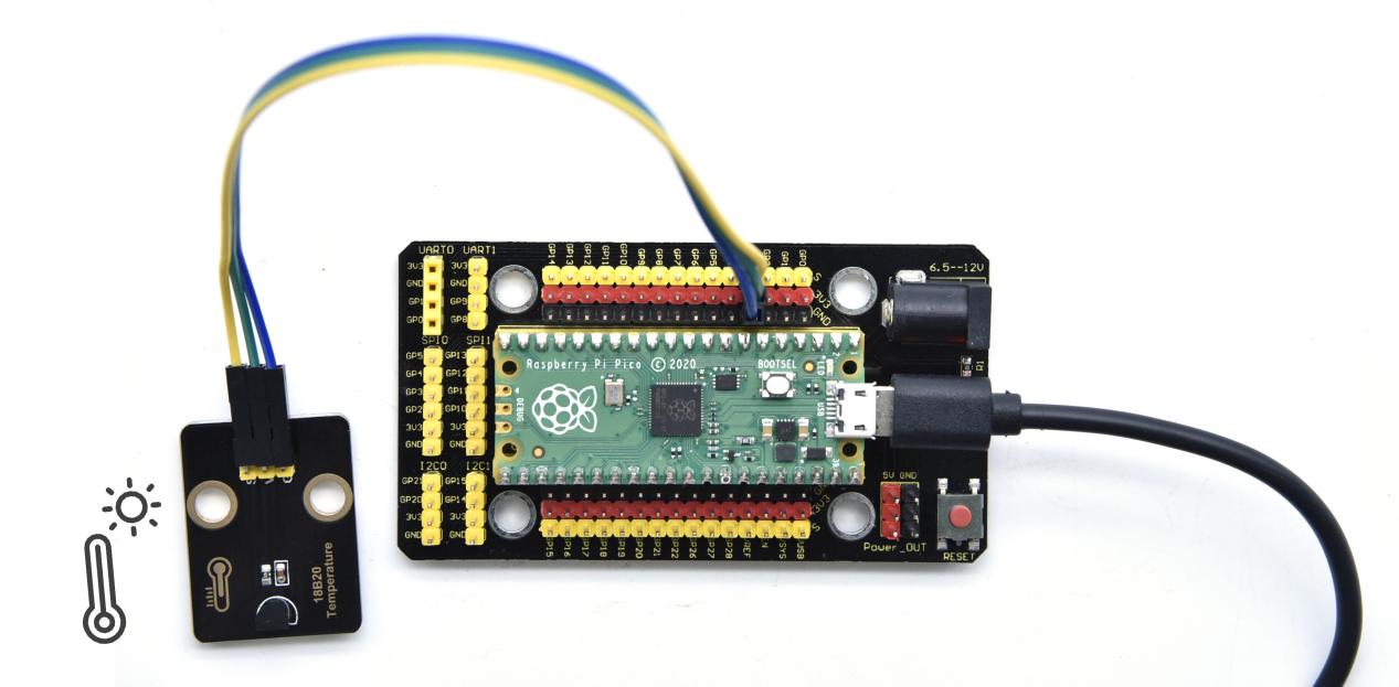
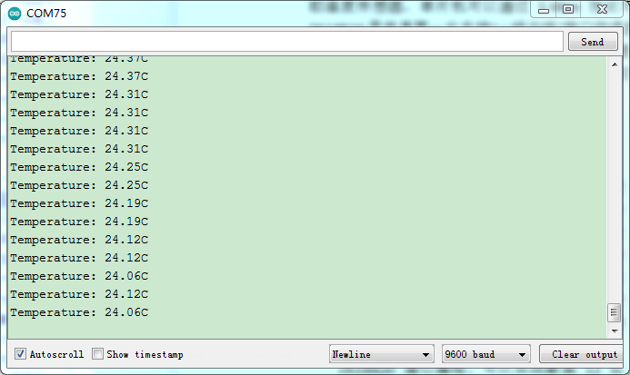
Project 36: XHT11 Temperature and Humidity Sensor
Description
This DHT11 temperature and humidity sensor is a composite sensor which contains a calibrated digital signal output of the temperature and humidity.
DHT11 temperature and humidity sensor uses the acquisition technology of the digital module and temperature and humidity sensing technology, ensuring high reliability and excellent long-term stability.
It includes a resistive element and a NTC temperature measuring device.
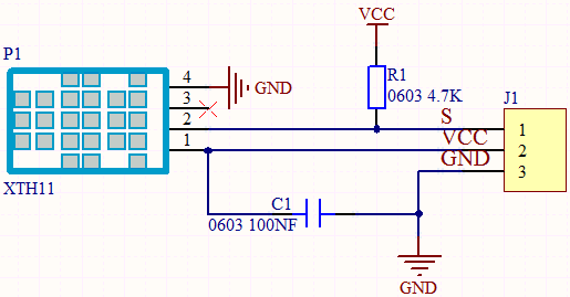
Working Principle
The communication and synchronization between the single-chip microcomputer and XHT11 adopts the single bus data format. The communication time is about 4ms. The data is divided into fractional part and integer part.
Operation process: A complete data transmission is 40bit, high bit first out. Data format: 8bit humidity integer data + 8bit humidity decimal data + 8bit temperature integer data + 8bit temperature decimal data + 8bit checksum
8-bit checksum: 8-bit humidity integer data + 8-bit humidity decimal data + 8-bit temperature integer data + 8-bit temperature decimal data “Add the last 8 bits of the result.
Required Components
|
|
|
|
|
| Raspberry Pi Pico Board*1 | Raspberry Pi Pico Expansion Board*1 | Keyestudio XHT11 Temperature and Humidity Sensor(compatible with DHT11)*1 | 3P Dupont Wire*1 | Micro USB Cable*1 |
Wiring Diagram
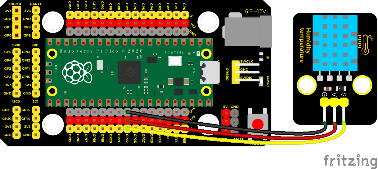
Test Code
/*
* Keyestudio 42 in 1 Starter Kit for Raspberry Pi Pico
* lesson 36
* xht11
* http://www.keyestudio.com
*/
#include “xht11.h”
//gpio22
xht11 xht(22);
unsigned char dht[4] = ;//only receive the data before 32 bit
**void setup() **
**void loop() else **
delay(1500); //wait for 1500ms
}
Code Explanation
In the experiment, we need to import the library file of XHT11 first.
We set the pin to GP22, and store the detected temperature and humidity data in the dht[4] array.
3. We add units behind the data. If the temperature unit is directly set to °C, the test results may be wrong, so we directly replace °C with C; the humidity unit is directly set to %.
Test Result
Upload the test code, power up, open the serial monitor and set baud rate to 9600. The monitor will display the temperature and humidity data, as shown below.
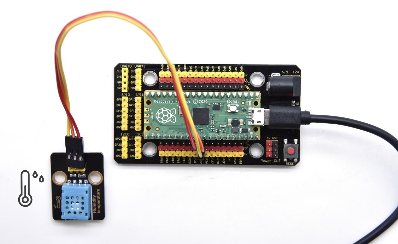
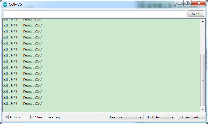
Project 37: DS1307 Clock Module
 Overview
The DS1307 serial real-time clock (RTC) is a low-power, full binary-coded decimal (BCD) clock/calendar plus 56 bytes of NV SRAM. Address and data are transferred serially through an I2C, bidirectional bus.
The clock/calendar provides seconds, minutes, hours, day, date, month, and year information. The end of the month date is automatically adjusted for months with fewer than 31 days, including corrections for leap year. The clock operates in either the 24-hour or 12-hour format with AM/PM indicator. The DS1307 has a built-in power-sense circuit that detects power failures and automatically switches to the backup supply.
Timekeeping operation continues while the part operates from the backup supply.
Working Principle
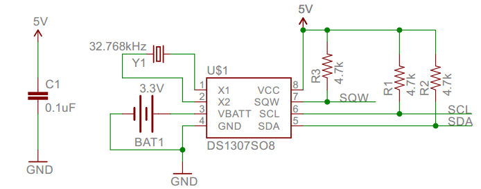
Detailed address and data:
Serial real-time clock records year, month, day, hour, minute, second and week; AM and PM indicate morning and afternoon respectively; 56 bytes of NVRAM store data; 2-wire serial port; programmable square wave output; power failure detection and automatic switching circuit; battery current is less than 500nA.
Pins description:X1, 32.768kHz crystal terminal ;
VBAT:X2:+3V input;
SDA:serial data;
SCL:serial clock;
SQW/OUT:square waves/output drivers
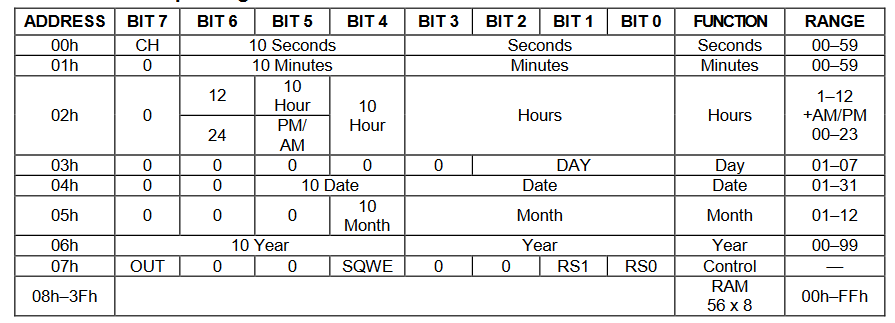
Components
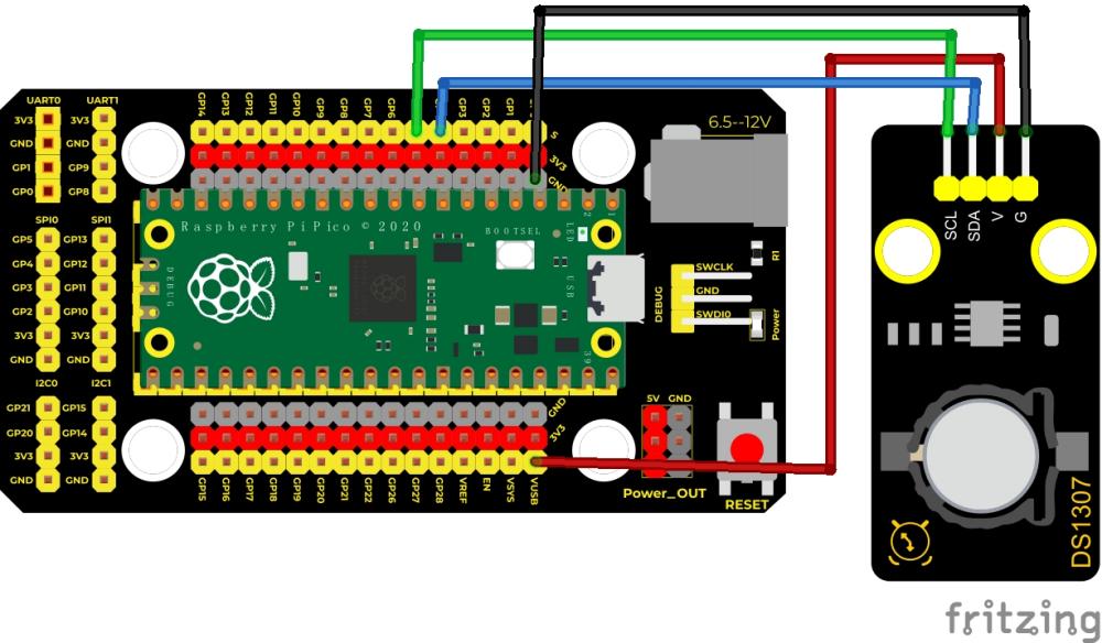
VUSB is 5V,then connect the power to VUSB.
Test Code
/*
Keyestudio 42 in 1 Starter Kit for Raspberry Pi Pico
lesson 37
DS1307 Real Time Clock
http://www.keyestudio.com
*/
#include <Wire.h>
#include “RtcDS1307.h” //library of the DS1307 clock module
RtcDS1307<TwoWire> Rtc(Wire);//i2c is connected to 14, 15
void setup()
void loop()
Code Explanation
We need to import the library of the clock module.
Rtc.GetDateTime(): the obtained current time and date.
**Rtc.Begin();**enable DS1307 real-time clock
Rtc.SetIsRunning(true); run the DS1307 real-time clock, if true changes into false, time will stop
**Rtc.SetDateTime();**set time
Rtc.GetDateTime().Year() return year
Rtc.GetDateTime().Month() return month
**Rtc.GetDateTime().Day()**return data
**Rtc.GetDateTime().Hour()**return hour
**Rtc.GetDateTime().Minute()**return minute
**Rtc.GetDateTime().Second()**return second
Rtc.GetDateTime().DayOfWeek() return week
Test Result
Upload the code power up by a USB cable, open the serial monitor and set baud rate to 9600.
We can see the displayed year, month, day, hour, minute, second and week on the shell, as shown below;
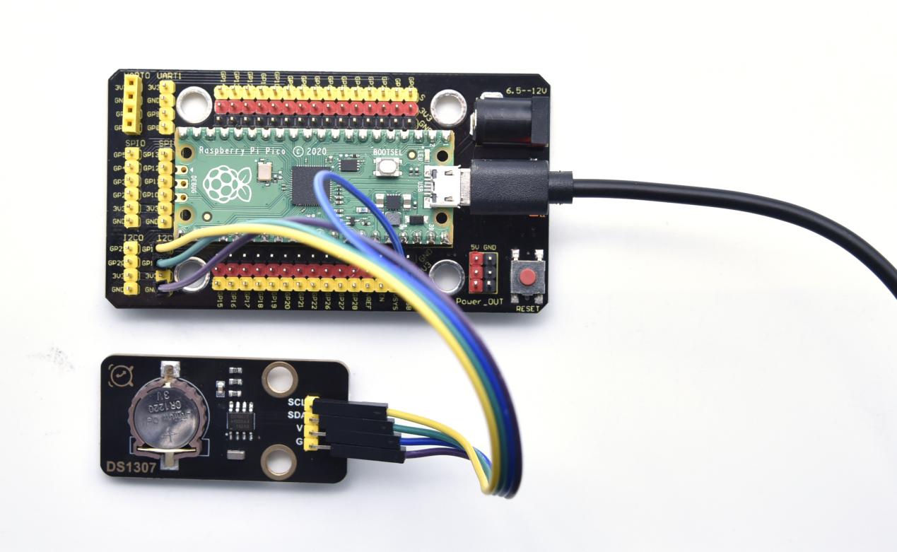
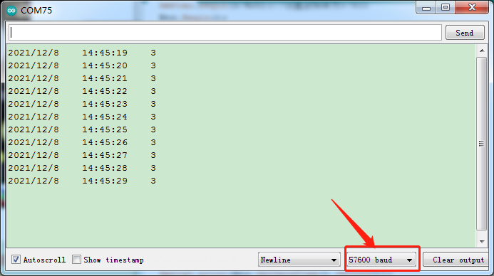
Project 38: ADXL345 Acceleration Sensor
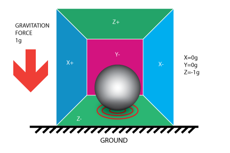
In this kit, there is a DIY electronic building block ADXL345 acceleration sensor module, which uses the ADXL345BCCZ chip. The chip is a small, thin, low-power 3-axis accelerometer with a high resolution (13 bits) and a measurement range of ±16g that can measure both dynamic acceleration due to motion or impact as well as stationary acceleration such as gravitational acceleration, making the device usable as a tilt sensor.

Working Principle
The ADXL345 is a complete 3-axis acceleration measurement system with a selection of measurement ranges of ±2 g, ±4 g, ±8 g or ±16 g. Its digital output data is in 16-bit binary complement format and can be accessed through an SPI (3-wire or 4-wire) or I2C digital interface.
The sensor can measure static acceleration due to gravity in tilt detection applications, as well as dynamic acceleration due to motion or impact. Its high resolution (3.9mg/LSB) enables measurement of tilt Angle changes of less than 1.0°.
Components Required
|
|
|
|
|
| Raspberry Pi Pico Board*1 | Raspberry Pi Pico Expansion Board*1 | Keyestudio ADXL345 Acceleration Module*1 | 4P Dupont Wire*1 | Micro USB Cable*1 |
Connection Diagram
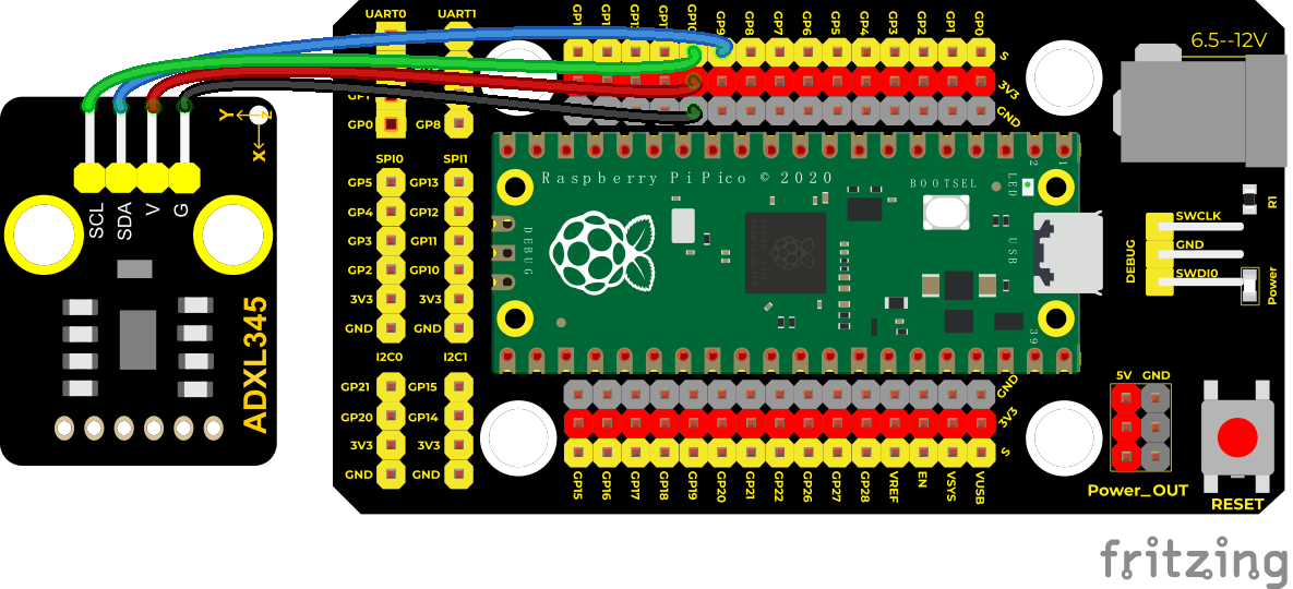
Test Code
/*
Keyestudio 42 in 1 Starter Kit for Raspberry Pi Pico
lesson 38
ADXL345
http://www.keyestudio.com
*/
#include “adxl345_io.h”
//the port is sda–>9,scl–>910
adxl345 adxl345(9, 10);
float out_X, out_Y, out_Z;
**void setup() **
**void loop() **
Code Explanation
Set 3 decimal variables out_X out_Y out_Z, and assign the measured result to out_X out_Y out_Z. The serial monitor displays the value of out_X out_Y out_Z, and the baud rate needs to be set before displaying (our default setting is 9600, which can be changed).
**Adxl345.Init;**Initialize the ADXX345 accelerometer
adxl345.readXYZ(&out_X, &out_Y, &out_Z);
Get the acceleration value of the X axis and return it to the variables out_X, out_Y, out_Z
Test Result
Upload the test code, power on with a USB cable, open the serial monitor
and set baud rate to 9600. The serial monitor displays the value
corresponding to the sensor, the unit is g, as shown in the figure
below. 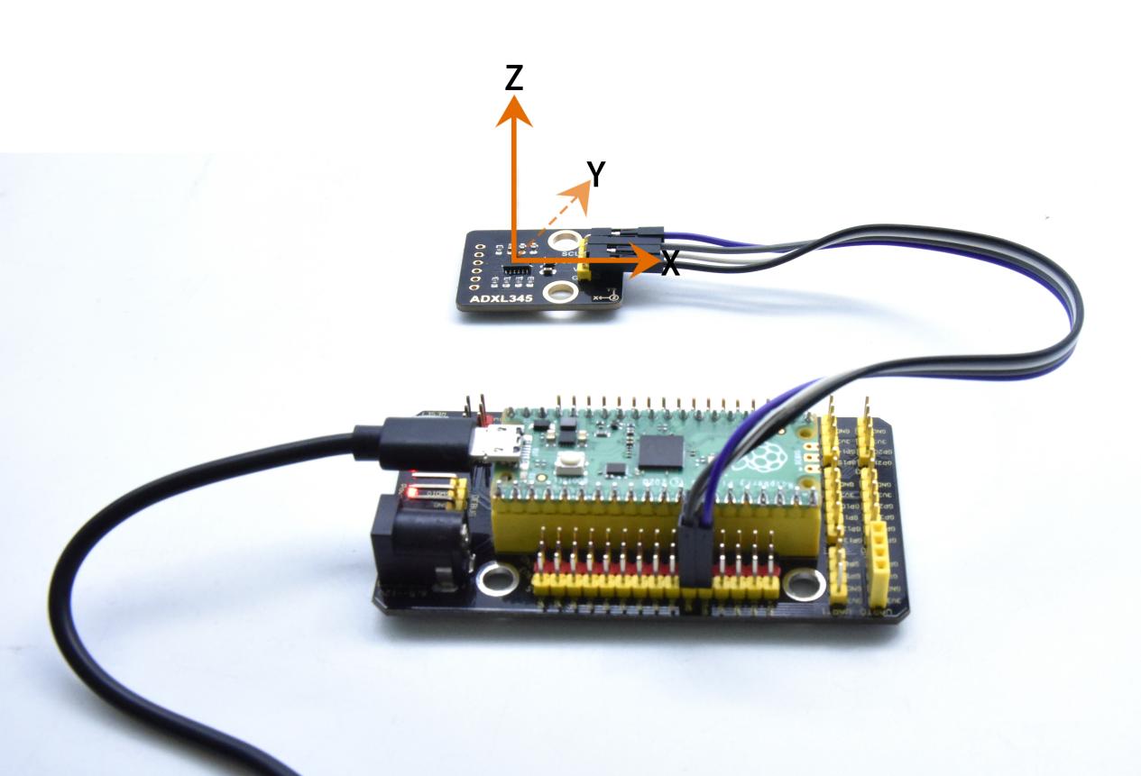
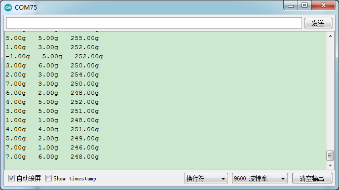
Project 39: TM1650 4-Digit Tube Display
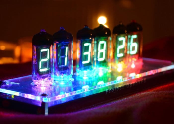
Overview
This module is mainly composed of a 0.36 inch red common anode 4-digit digital tube, and its driver chip is TM1650. When using it, we only need two signal lines to make the single-chip microcomputer control a 4-bitdigit tube, which greatly saves the IO port resources of the control board.
TM1650 is a special circuit for LED (light emitting diode display) drive control. It integrates MCU input and output control digital interface, data latch, LED drivers, keyboard scanning, brightness adjustment and other circuits.
TM1650 has stable performance, reliable quality and strong anti-interference ability.
It can be applied to the application of long-term continuous working for 24 hours.
TM1650 uses 2-wire serial transmission protocol for communication (note that this data transmission protocol is not a standard I2C protocol). The chip can drive the digital tube and save MCU pin resources through two pins and MCU communication.
Working Principle
TM1650 adopts IIC treaty and SDA and SCL wire
Data command setting is 0x48. This means that lighting up the tube display not perform its button scanning function.
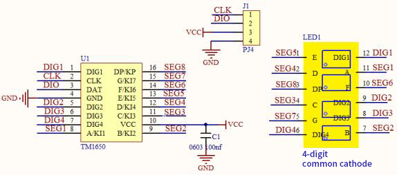
Data command setting: 0x48 means that we light up the digital tube, instead of enable the function of key scanning
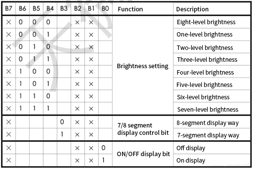
Command display setting:
bit[6:4]: set the brightness of tube display, and 000 is brightest
bit[3]: set to show decimal points
bit[0]: start the display of the tube display
Components
|
|
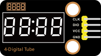 |
|
|
| Raspberry Pi Pico Board*1 | Raspberry Pi Pico Shield*1 | Keyestudio TM1650 4-Digit Tube Display*1 | 4P Dupont Wire*1 | Micro USB Cable*1 |
Wiring Diagram
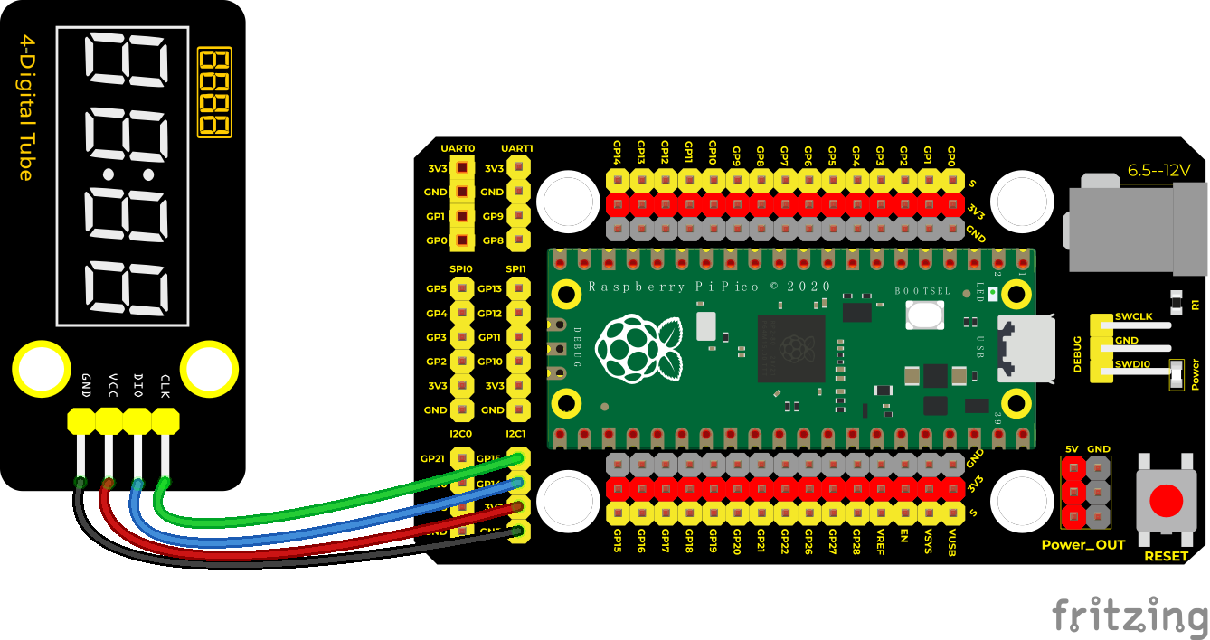
Test Code
/*
Keyestudio 42 in 1 Starter Kit for Raspberry Pi Pico
lesson 39
TM1650 Four digital tube
http://www.keyestudio.com
*/
#include “KETM1650.h” //import the library file of TM1650
int item = 0; //display value
//pins are GP14 and GP15
#define DIO 14
#define CLK 15
KETM1650 tm_4display(CLK, DIO);
**void setup() **
**void loop() **
delay(100); //delay in 100ms
}
Code Explanation
Similarly, we need to import the library file of the TM1650 module first. Here are some commonly used function interfaces:
.init(); Initialize TM1650
**.clear();**clear up the tube display
**.displayString(char *aString);**Display character string,
.displayString(String sString); Display string ,sString is character string
.displayString(float value);Display decimal, the content is float type
.displayString(double value);Display decimal, the content is double type
.displayString(int value); Display integer, the content is int type
**.displayOn();**open the tube display
.displayOff(); turn off the tube display,in comparison with .clear,once turning off, the function .displayOn() must be used;
.setDot(unsigned int aPos, bool aState); display decimal point, aPos is the location of decimal point (0~3) corresponds to (1~4),aState is the display status:1(true)lights up,2(false)goes off.
.setBrightness(unsigned int iBrightness); set the brightness of the tube display
iBrightness: the brightness value(1~8, type is unsigned int,
Test Result
Run the test code, wire up and power on. 4-digit tube display will show integer from 0 to 99999, add 1 for each 10ms. Increase to 9999 then start from 0
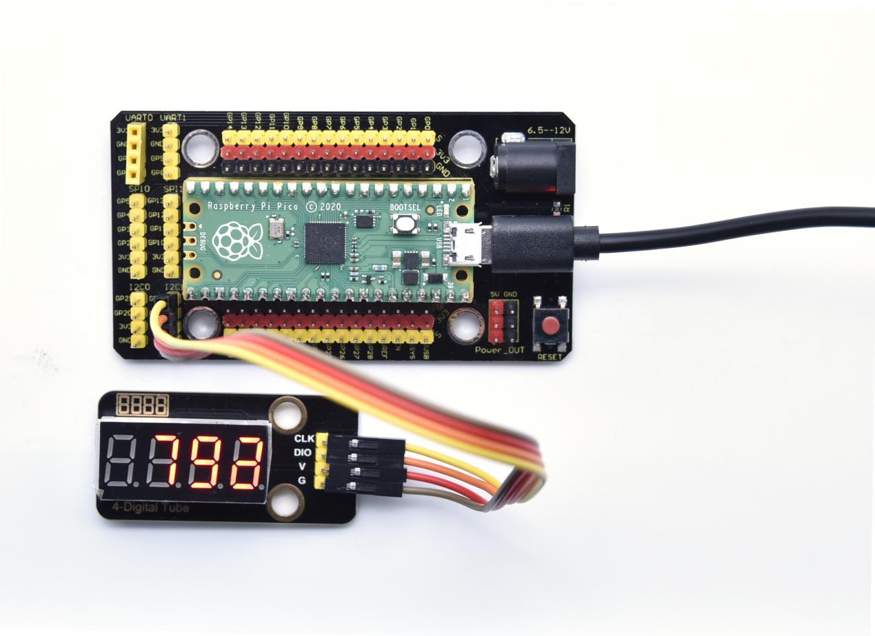
Project 40: HT16K33_8X8 Dot Matrix Module

Overview
What is the dot matrix display?
The 8X8 dot matrix is composed of 64 light-emitting diodes, and each light-emitting diode is placed at the intersection of the row line and the column line. When the corresponding row is set to 1 level, and a certain column is set to 0 level, the corresponding diode will light up.
Working Principle
As the schematic diagram shown, to light up the LED at the first row and column, we only need to set C1 to high level and R1 to low level. To turn on LEDs at the first row, we set R1 to low level and C1-C8 to high level.
16 IO ports are needed, which will highly waste the MCU resources.
Therefore, we designed this module, using the HT16K33 chip to drive an 8*8 dot matrix, which greatly saves the resources of the single-chip microcomputer.
There are three DIP switches on the module, all of which are set to I2C communication address. The setting method is shown below.
| A0(1) | A1(2) | A2(3) | A0(1) | A1(2) | A2(3) | A0(1) | A1(2) | A2(3) |
| 0(OFF) | 0(OFF) | 0(OFF) | 1(ON) | 0(OFF) | 0(OFF) | 0(OFF) | 1(ON) | 0(OFF) |
| OX70 | OX71 | OX72 | ||||||
| A0(1) | A1(2) | A2(3) | A0(1) | A1(2) | A2(3) | A0(1) | A1(2) | A2(3) |
| 1(ON) | 1(ON) | 0(OFF) | 0(OFF) | 0(OFF) | 1(ON) | 1(ON) | 0(OFF) | 1(ON) |
| OX73 | OX74 | OX75 | ||||||
| A0(1) | A1(2) | A2(3) | A0(1) | A1(2) | A2(3) | |||
| 0(OFF) | 1(ON) | 1(ON) | 1(ON) | 1(ON) | 1(ON) | |||
| OX76 | OX77 |
A0,A1 and A2 are grounded, that is, the address is 0x70
Components
|
|
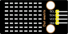 |
|
|
| Raspberry Pi Pico Board*1 | Raspberry Pi Pico Shield*1 | Keyestudio HT16K33_ 8X8 Dot Matrix*1 |
4P Dupont Wire*1 | Micro USB Cable*1 |
Wiring Diagram
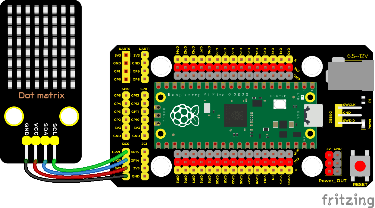
Test Code
/*
Keyestudio 42 in 1 Starter Kit for Raspberry Pi Pico
lesson 40
HT16K33 8*8 dot matrix
http://www.keyestudio.com
*/
#include <Matrix.h>//the library of the dot matrix
Matrix myMatrix(20, 21);
uint8_t LEDArray[8];
const uint8_t LedArray1[8] PROGMEM = ;//heart beat pattern
**void setup() **
**void loop() **
}
myMatrix.write(); //display
}
Code Explanation
First we need to import the library file.
The pattern in our code is an array of byte data type, which is shown in the table below. We convert into binary, and fill in the 8*8 form below to make it clear. 1 means on, 0 means off,
Then we can see that it is a heart shape.
| 0 | 0 | 0 | 0 | 0 | 0 | 0 | 0 |
| 0 | 0 | 0 | 1 | 1 | 0 | 0 | 0 |
| 0 | 0 | 1 | 1 | 1 | 1 | 0 | 0 |
| 0 | 1 | 1 | 1 | 1 | 1 | 1 | 0 |
| 1 | 1 | 1 | 1 | 1 | 1 | 1 | 1 |
| 1 | 1 | 1 | 1 | 1 | 1 | 1 | 1 |
| 0 | 1 | 1 | 0 | 0 | 1 | 1 | 0 |
| 0 | 0 | 0 | 0 | 0 | 0 | 0 | 0 |
Test Result
Burn the test code and wire up according to the wiring diagram; after powering on, the dot matrix will display a heart beat pattern.
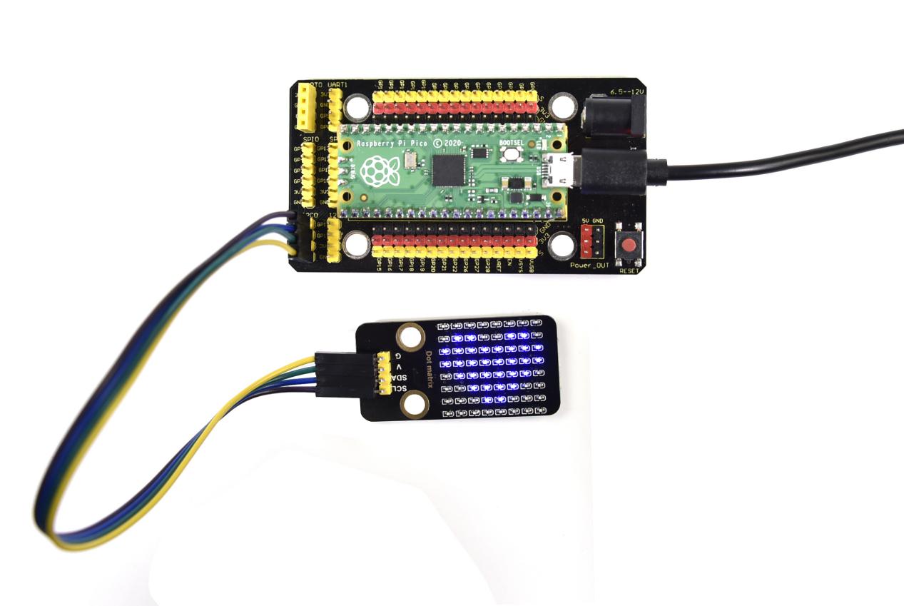
Project 41: LCD_128X32_DOT Module

This is a 128*32 pixel LCD module, which uses IIC communication mode and ST7567A driver chip . At the same time, the code contains all the English letters and common symbols of the library that can be directly called. When used, we can also set English letters and symbols to display different text sizes in our code. To make it easy to set up the pattern display, we also provide a mold capture software that can convert a specific pattern into control code and then copy it directly into the test code for use.
In the experiment, we will set up the display screen to display various English words, common symbols and numbers.
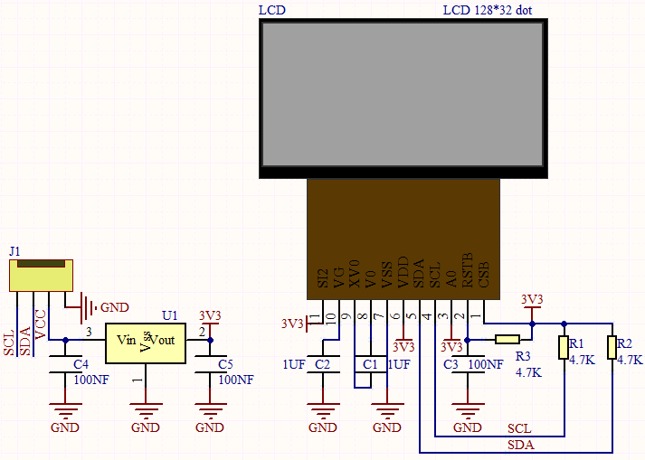
Components Required
|
|
|
|
|
| Raspberry Pi Pico Board*1 | Raspberry Pi Pico Expansion Board*1 | Keyestudio LCD_128X32_DOT Module*1 | 4P Dupont Wire*1 | Micro USB Cable*1 |
Connection Diagram
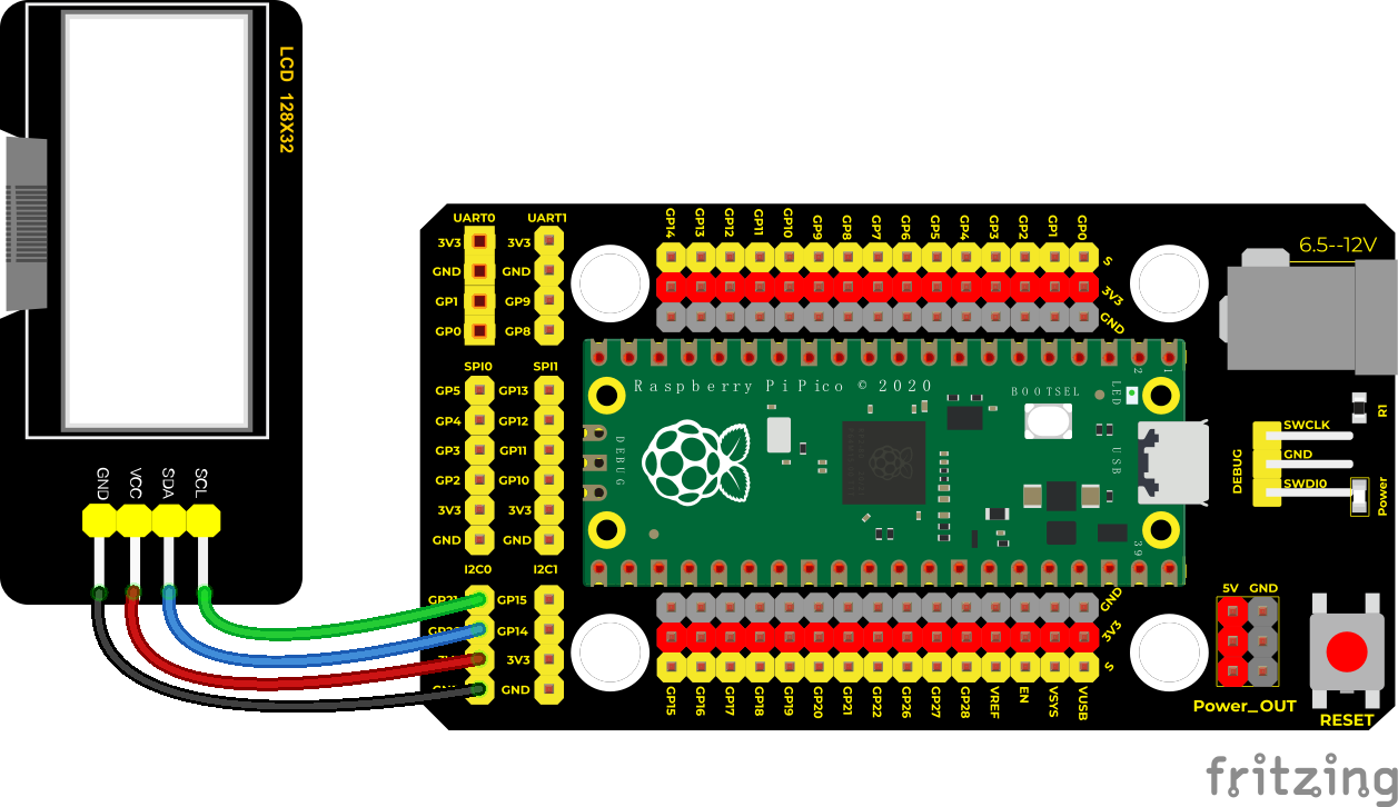
Test Code/*
Keyestudio 42 in 1 Starter Kit for Raspberry Pi Pico
lesson 41
lcd128*32
http://www.keyestudio.com
*/
#include “lcd128_32_io.h”
//Create an instance of lcd12832, sda—>20, scl—>21
lcd lcd(20, 21);
**void setup() **
void loop() :;’|?,.~\[]”);
}
Code Explanation
First import the library file
.Init() initializes the display screen; .Clear() clears the display; .Cursor() sets the display position; .Display() displays characters;
Test Result
After uploading the test code, wire up and power up, the first line of the 128X32LCD module display shows “KEYES”, the second line shows “ABCDEFGHIJKLMNOPQR”, and the third line shows “123456789+-*/<> =$@”, the fourth line displays “%^&(){}:;’|?,.~\[]”, as shown in the following figure:
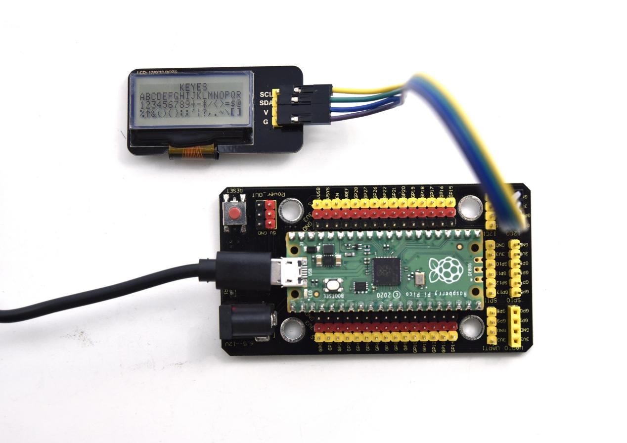
Project 42: RFID Module

Description
RFIDRFID-RC522 radio frequency module adopts a Philips MFRC522 original chip to design card reading circuit, easy to use and low cost, suitable for equipment development and card reader development and so on.
RFID or Radio Frequency Identification system consists of two main components, a transponder/tag attached to an object to be identified, and a Transceiver also known as interrogator/Reader.
In the experiment, the data read by the card swipe module is 4 hexadecimal numbers, and we print these four hexadecimal numbers as strings. For example, we read the data of the IC card below: 0x8d, 0xfe, 0x6c, 0x4d, and the information string displayed in the shell is 8dfe6c4d; the data read from the keychain is: 0xbc, 0x33, 0x76, 0x6e, and the information is displayed in the shell The string is bc33766e. Sometimes I see that there are only 7 bits because there is a 0 in the front omitted, such as 0a, it displays a.
Working Principle
RFID (Radio Frequency Identification)
Radio frequency identification, the card reader is composed of a radio frequency module and a high-level magnetic field. The Tag transponder is a sensing device, and this device does not contain a battery. It only contains tiny integrated circuit chips and media for storing data and antennas for receiving and transmitting signals. To read the data in the tag, first put it into the reading range of the card reader. The reader will generate a magnetic field, and because the magnetic energy generates electricity according to Lenz’s law, the RFID tag will supply power, thereby activating the device.
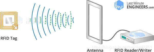
Required Components
|
|
|
|
| Raspberry Pi Pico Board*1 | Raspberry Pi Pico Expansion Board*1 | Keyestudio DIY RFID Module*1 | 4P Dupont Wire*1 |
|
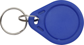 |
 |
|
| Micro USB Cable*1 | Key*1 | IC Card*1 |
Wiring Diagram
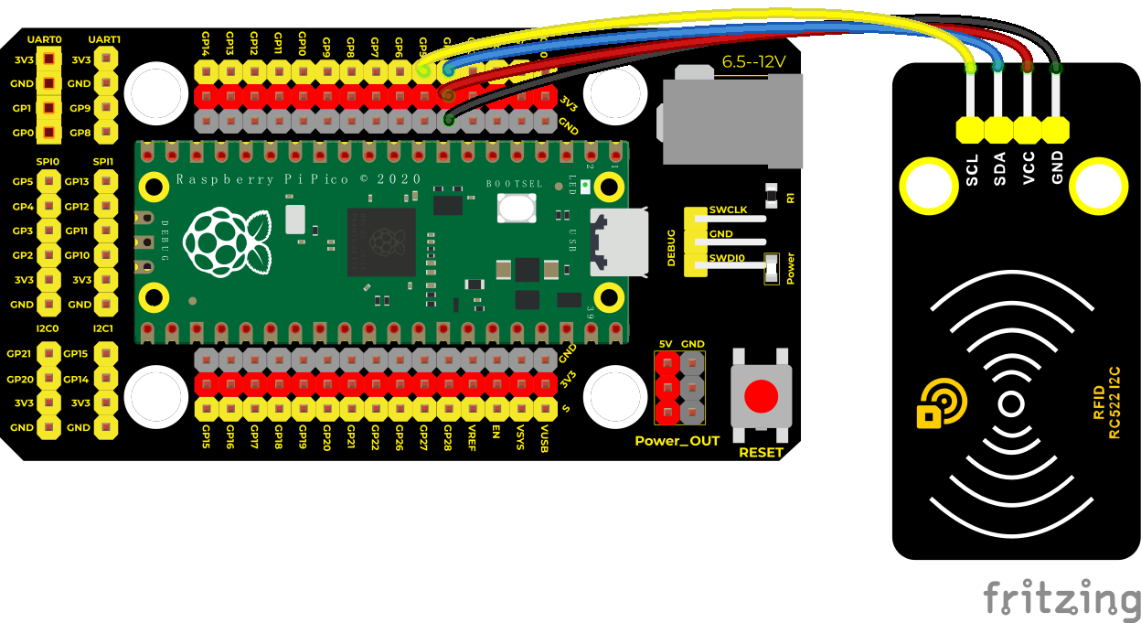
Test Code
/*
* Keyestudio 42 in 1 Starter Kit for Raspberry Pi Pico
* lesson 42
* mfrc522
* http://www.keyestudio.com
*/
#include <Wire.h>
#include “MFRC522_I2C.h”
//iic pins default to pico’s 4 and 5
// 0x28 is the i2c address on SDA. If it doesn’t match, check your address with i2cscanner
MFRC522 mfrc522(0x28); // 创建 MFRC522 实例。
String rfid_str = “”;
**void setup() **
**void loop() **
rfid_str = “”;//String empty
Serial.print(F(“Card UID:”));
**for (byte i = 0; i < mfrc522.uid.size; i++) **
Serial.println(rfid_str);
}
Code Explanation
First import the library file of RFID522.
Wire.begin(); The module we use is the IIC interface, so we first initialize the IIC
mfrc522.PCD_Init(); initialize MFRC522
String(mfrc522.uid.uidByte[i], HEX); A string to convert the value read into hexadecimal format
Test Result
Wire up, run the test code, power up and open the monitor and set baud rate to 9600.When we make the IC card close to the RFID module, the information will be printed out, as shown in the figure below.
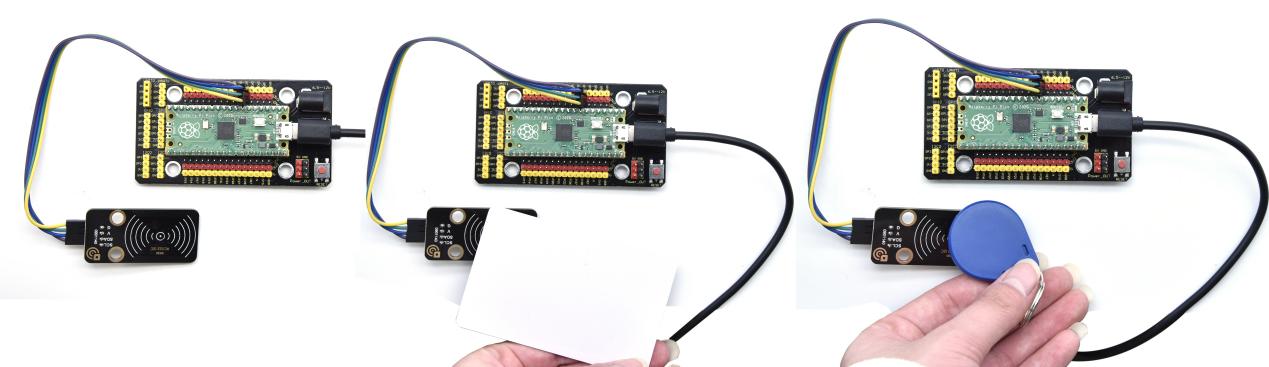
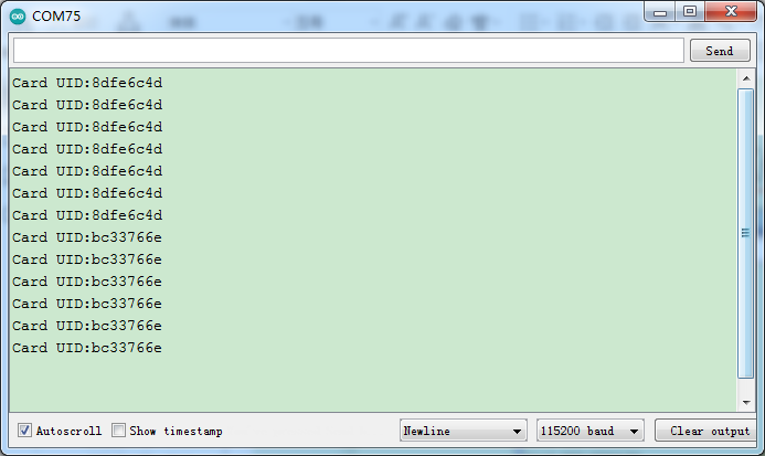
5. Comprehensive Experiments
The previous projects are related to single sensor or module. In the following part, we will combine various sensors and modules to create some comprehensive experiments to perform special functions.
Project 43: Breathing LED

Overview
A“breathing LED”is a phenomenon where an LED’s brightness smoothly changes from dark to bright and back to dark, continuing to do so and giving the illusion of an LED“breathing. This phenomenon is similar to a lung breathing in and out. So how to control LED’s brightness? We need to take advantage of PWM.
Components
|
|
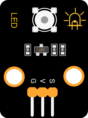 |
|
|
| Raspberry Pi Pico Board*1 | Raspberry Pi Pico Shield*1 | Keyestudio White LED Module*1 | 3P Dupont Wire*1 | Micro USB Cable*1 |
Wiring Diagram
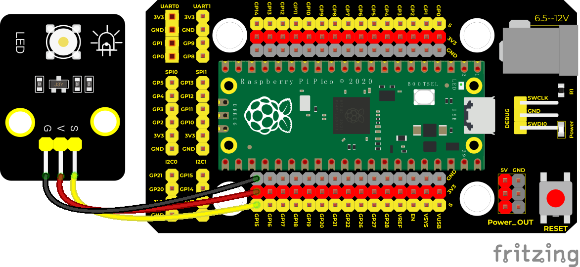
Test Code/*
* Keyestudio 42 in 1 Starter Kit for Raspberry Pi Pico
* lesson 43
* Breath
* http://www.keyestudio.com
*/
int LED = 15; //the pin of LED is connected to GP15
**void setup() **
**void loop() **
**for (int i = 255; i >= 0; i–) **
}
Code Explanation
The function for (int i = 0; i <= 255; i = i + 1);indicate the variable 1 adds by 1 from 0 to 255, until it doesn’t meet with i <= 255. It will execute the code for 256 times.
Equally, for (int i = 255; i >= 0; i = i - 1) means reducing by 1 for each time.
When not meeting with i>= 0,jump out the for() loop,execute the code for 256 times
In the code, we control the brightness of the LED on the module by setting the PWM value. In the experiment, we connect the module signal to the pin GPIO15. The smaller the PWM value, the darker the LED on the module; on the contrary, the larger the value, the brighter the LED on the module, the range is 0-255.
analogWrite (pin, value): pin is the PWM port, value is the PWM value to be output (0~255).
Set the PWM output value of GP15 to i. At the beginning, i increased from 0 to 255, and up by 1 each time. Each time delaying in 10ms, the LED on the module gradually will brighten. When PWM is 255, i begins to decrease from 255 to 0, down by 1 for each time.
Each time delaying in 10ms, the LED on the module will gradually get dim. Then it will become brighter, cyclically alternating, just like human breathe.
We can change the delayed time in the code. There are two ways:
Change the step length or reduce the delayed time.
The step length is supposed to divided by 255, like 3 and 5. 3 means increasing by 3, -3 means reducing by 3.
Test Result
Run the test code, the LED on the module gradually gets dimmer then brighter, cyclically, like human breathe
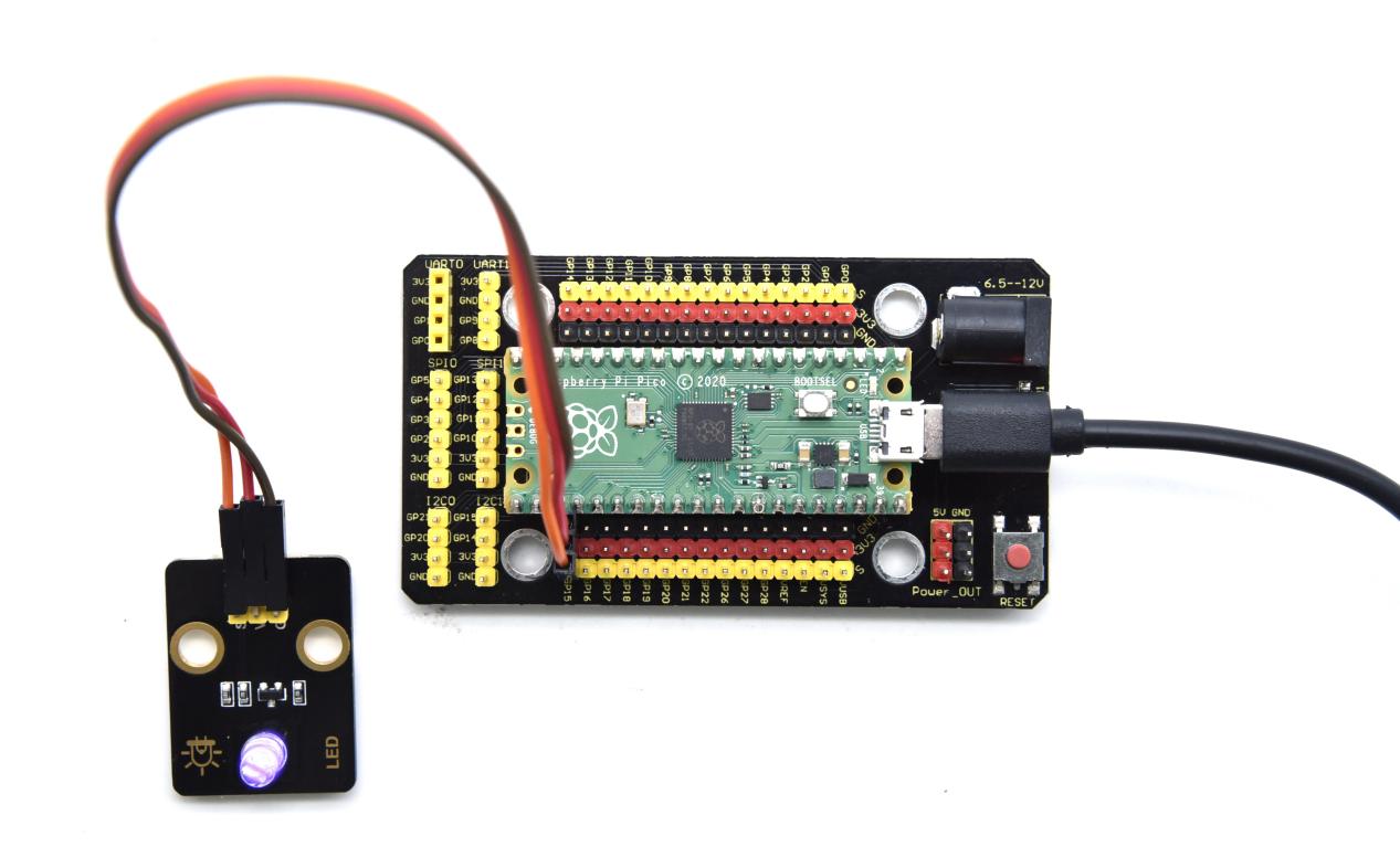
Project 44: Button-controlled LED
Overview
In this lesson, we will make an extension experiment with a button and an LED. When the button is pressed and low levels are output, the LED will light up; when the button is released, the LED will go off. Then we can control a module with another module.
Components
|
|
|
 |
|
|
| Raspberry Pi Pico Board*1 | Raspberry Pi Pico Shield*1 | Keyestudio White LED Module*1 | Keyestudio DIY Button Module*1 | 3P Dupont Wire*2 | Micro USB Cable*1 |
Wiring Diagram
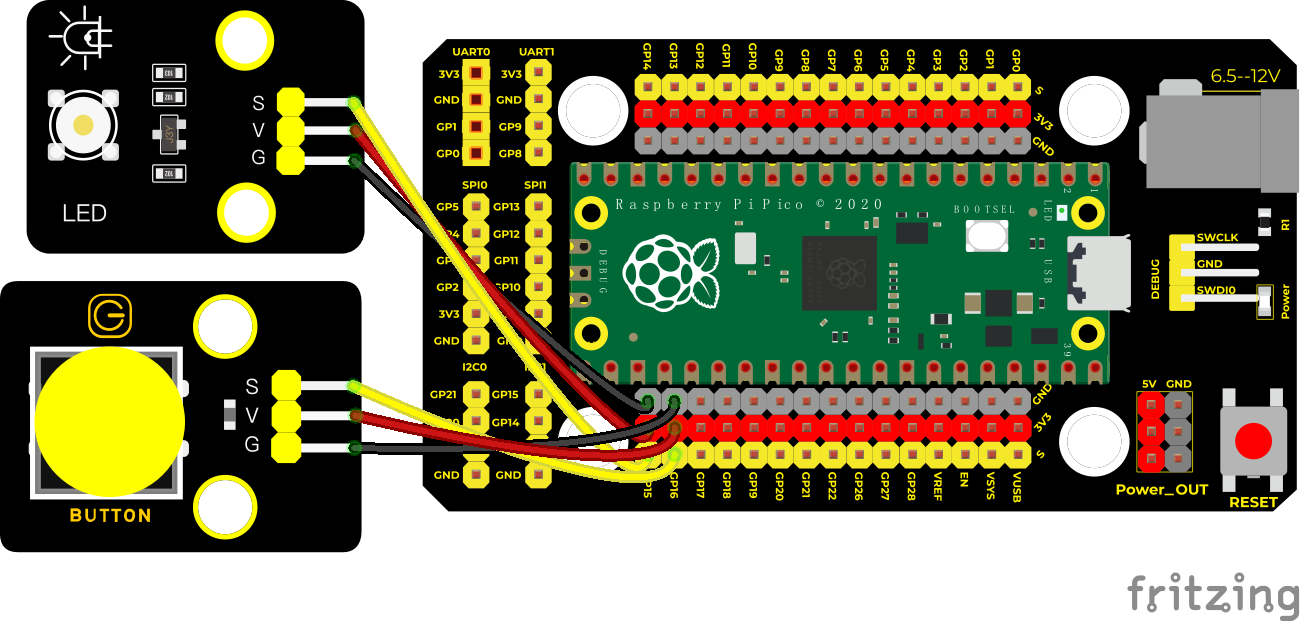
Test Code
/*
* Keyestudio 42 in 1 Starter Kit for Raspberry Pi Pico
* lesson 44
* button control LED
* http://www.keyestudio.com
*/
int button = 16;//the digital pin of the button is 16
int led = 15;//the pin of LED is connected to GP15
bool led_flag;
**void setup() **
**void loop() **
void toggle_handle()
Code Explanation
Set IO ports according to connection diagram and configure pins mode
attachInterrupt(digitalPinToInterrupt(button), toggle_handle, FALLING)
The trigger mode is when a high level becomes a low level. When the trigger interrupts, the interrupt function will be activated.
toggle_handle: when entering the interrupt mode, the on and off of the LED can be controlled.
Test Result
Upload the code wire up and power up with a USB cable. When the button is pressed, the LED will light up; when pressed again, the LED will go off.
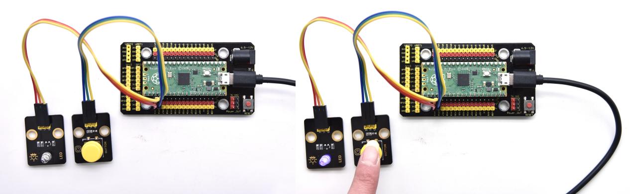
Project 45: Alarm Experiment

Overview
In the previous experiment, we control an output module though an input module. In this lesson, we will make an experiment that the active buzzer will emit sounds once an obstacle appears.
Components
|
|
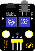 |
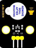 |
|
|
| Raspberry Pi Pico Board*1 | Raspberry Pi Pico Shield*1 | Keyestudio Obstacle Avoidance Sensor*1 | Keyestudio Active Buzzer*1 | 3P Dupont Wire*2 | Micro USB Cable*1 |
Wiring Diagram
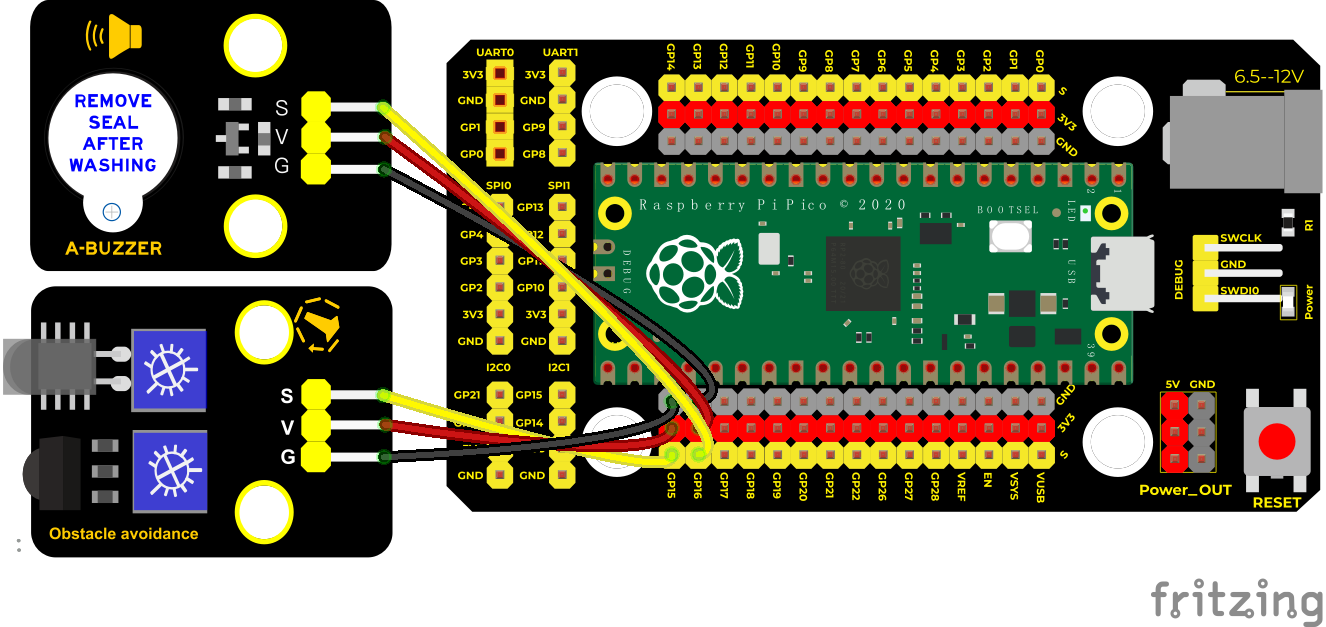
Test Code
/*
* Keyestudio 42 in 1 Starter Kit for Raspberry Pi Pico
* lesson 45
* Avoiding alarm
* http://www.keyestudio.com
*/
int item = 0;
**void setup() **
**void loop() else **
delay(100);//delay in 1000ms
}
Code Explanation
Set IO ports according to connection diagram then configure pins mode
The value is 0 when pressing the button, So, we can determine the key value(0)through if (item == 0) and make the buzzer beep.
Test Result
Upload the test code, if the obstacle is detected, the active buzzer will chime; if not, it won’t beep
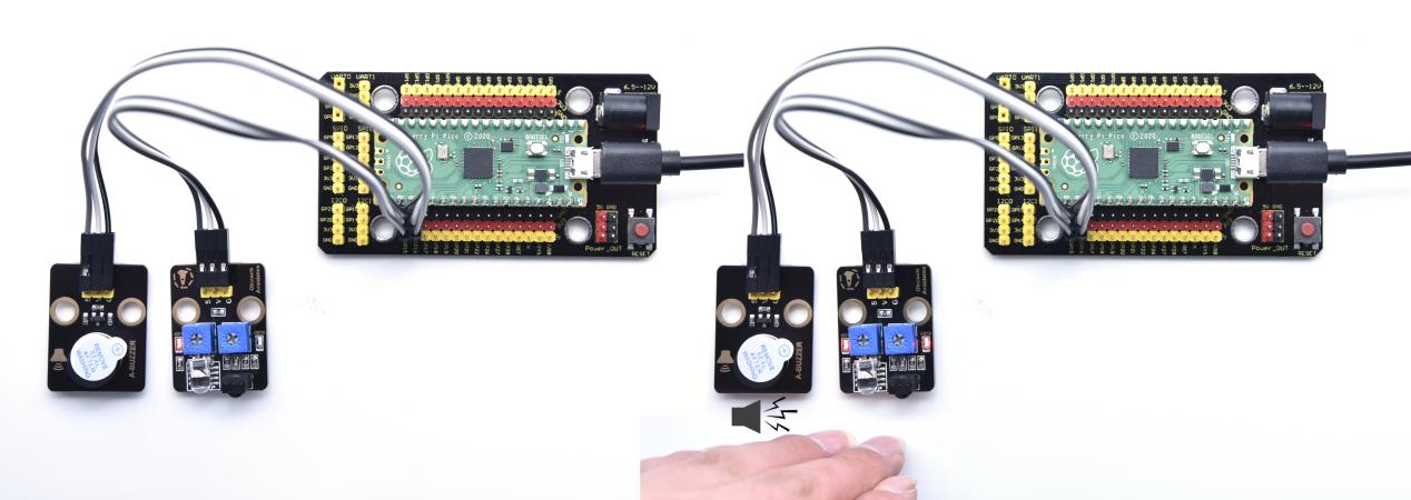
Project 46: Ultraviolet Alarm
Description
We can use a UV sensor to control the buzzer to achieve the effect of UV alarm.
Required Components
|
|
|
|
|
|
| Raspberry Pi Pico Board*1 | Raspberry Pi Pico Expansion Board*1 | Keyestudio ultraviolet Sensor*1 | Keyestudio Active Buzzer*1 | 3P Dupont Wire*2 | Micro USB Cable*1 |
Wiring Diagram
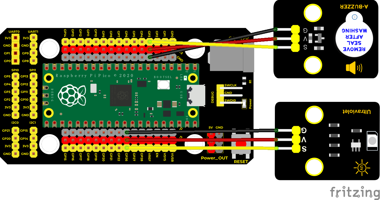
Test Code
/*
* Keyestudio 42 in 1 Starter Kit for Raspberry Pi Pico
* lesson 46
* http://www.keyestudio.com
*/
int item = 0;
**void setup() **
**void loop() else **
delay(100);//delay in 100ms
}
Test Result
Wire up, run the test code and power on. We use an ultraviolet sensor to detect and if the strength of ultraviolet rays reach what we set, the active buzzer will emit sound.
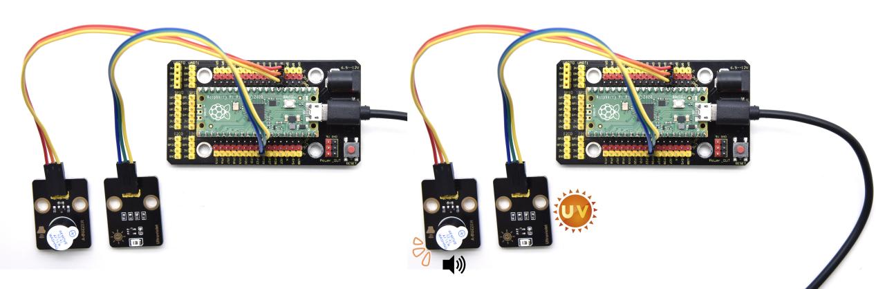
Project 47: PIR Motion Sensor
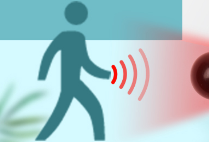
Introduction
In this experiment, we will control an active buzzer and an on-board LED through a PIR motion sensor.
Components
|
|
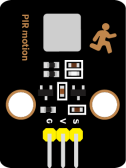 |
 |
|
|
| Raspberry Pi Pico Board*1 | Raspberry Pi Pico Shield*1 | Keyestudio PIR Motion Sensor*1 | Keyestudio Active Buzzer*1 | 3P Dupont Wire*2 | Micro USB Cable*1 |
Connection Diagram
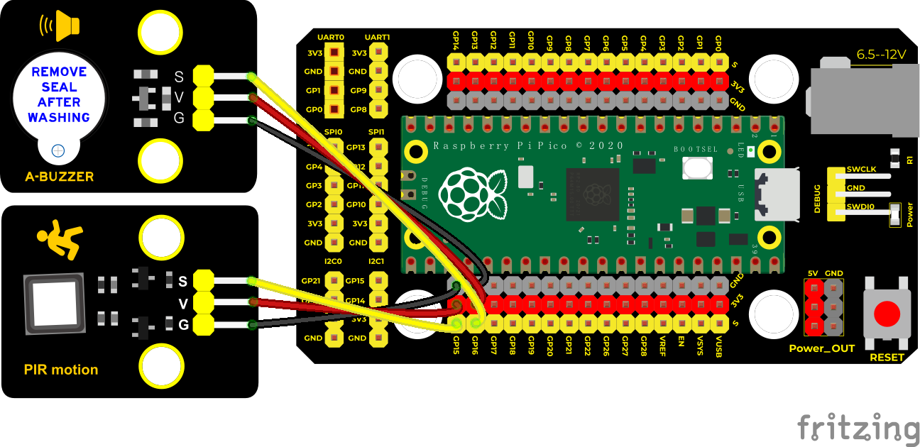
Test Code
/*
* Keyestudio 42 in 1 Starter Kit for Raspberry Pi Pico
* lesson 47
* PIR alarm
* http://www.keyestudio.com
*/
int item = 0;
**void setup() **
**void loop() else **
}
Test Result
Upload the test code wire up and power on. if the sensor detects people moving, the external active buzzer will chime; if not, it won’t beep.
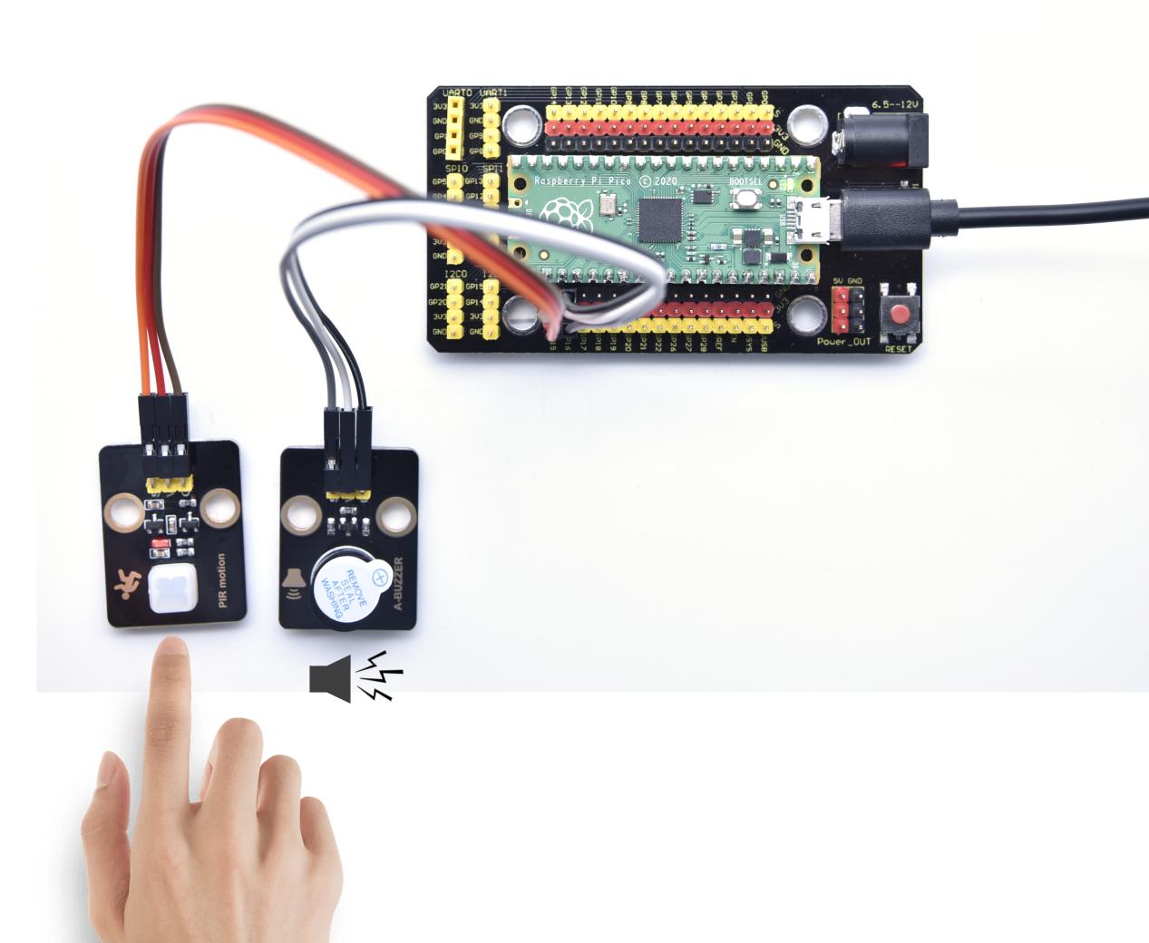
Project 48: Speaker Module

Introduction
We learned about controlling the speaker module to make sounds, play beats and adjust its volume. In fact, each song is a combination of specific beats and tones (frequencies). In this experiment, we use this speaker module to play a song.
The frequency of each tone is shown below.
Bass:
Key Note |
1# | 2# | 3# | 4# | 5# | 6# | 7# |
| A | 221 | 248 | 278 | 294 | 330 | 371 | 416 |
| B | 248 | 278 | 294 | 330 | 371 | 416 | 467 |
| C | 131 | 147 | 165 | 175 | 196 | 221 | 248 |
| D | 147 | 165 | 175 | 196 | 221 | 248 | 278 |
| E | 165 | 175 | 196 | 221 | 248 | 278 | 312 |
| F | 175 | 196 | 221 | 234 | 262 | 294 | 330 |
| G | 196 | 221 | 234 | 262 | 294 | 330 | 371 |
Midrange :
Key Note |
1 | 2 | 3 | 4 | 5 | 6 | 7 |
| A | 441 | 495 | 556 | 589 | 661 | 724 | 833 |
| B | 495 | 556 | 624 | 661 | 724 | 833 | 935 |
| C | 262 | 294 | 330 | 350 | 393 | 441 | 495 |
| D | 294 | 330 | 350 | 393 | 441 | 495 | 556 |
| E | 330 | 350 | 393 | 441 | 495 | 556 | 624 |
| F | 350 | 393 | 441 | 495 | 556 | 624 | 661 |
| G | 393 | 441 | 495 | 556 | 624 | 661 | 724 |
Treble:
Key Note |
1# | 2# | 3# | 4# | 5# | 6# | 7# |
| A | 882 | 990 | 1112 | 1178 | 1322 | 1484 | 1665 |
| B | 990 | 1112 | 1178 | 1322 | 1484 | 1665 | 1869 |
| C | 525 | 589 | 661 | 700 | 786 | 882 | 990 |
| D | 589 | 661 | 700 | 786 | 882 | 990 | 1112 |
| E | 661 | 700 | 786 | 882 | 990 | 1112 | 1248 |
| F | 700 | 786 | 882 | 935 | 1049 | 1178 | 1322 |
| G | 786 | 882 | 990 | 1049 | 1178 | 1322 | 1484 |
Beats are the time delay for each note. The larger the number, the longer the delay time. A note without a line in the spectrum is a beat, with a delay of 1s. while a beat with an underline is 1/2 of a beat without a line, with a delay of 0.5s, and a beat with two underlines is 1/4 of a beat without a line, with a delay of 0.25s. The 1/8 of a beat is with a delay of 0.125s.
We will take Happy Birthday Song as an example.
Components
|
|
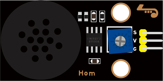 |
|
|
| Raspberry Pi Pico Board*1 | Raspberry Pi Pico Expansion Board*1 | Keyestudio 8002b Audio Power Amplifier*1 | 3P Dupont Wire*1 | MicroUSB Cable*1 |
Connection Diagram
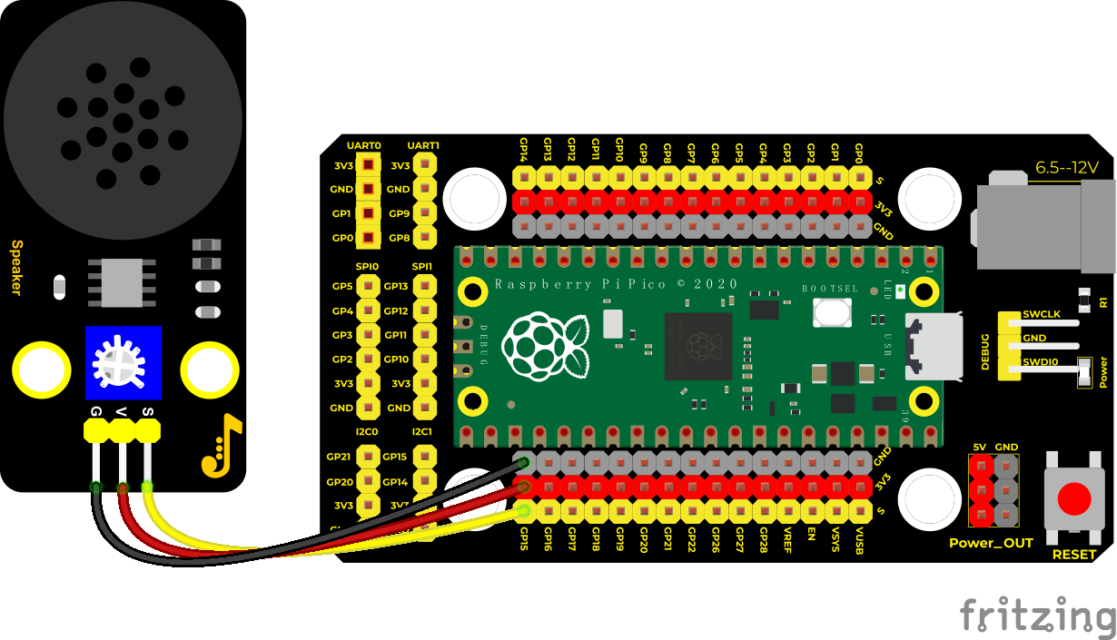
Test Code
/*
* Keyestudio 42 in 1 Starter Kit for Raspberry Pi Pico
* lesson 48
* play music
* http://www.keyestudio.com
*/
#define D0 -1
#define D1 262
#define D2 293
#define D3 329
#define D4 349
#define D5 392
#define D6 440
#define D7 494
#define M1 523
#define M2 586
#define M3 658
#define M4 697
#define M5 783
#define M6 879
#define M7 987
#define H1 1045
#define H2 1171
#define H3 1316
#define H4 1393
#define H5 1563
#define H6 1755
#define H7 1971
//List all the frequencies of the D key
#define WHOLE 1
#define HALF 0.5
#define QUARTER 0.25
#define EIGHTH 0.25
#define SIXTEENTH 0.625
//list all beats
int tune[] = //List the frequencies according to the numbered musical notation
;
float durt[] = //List the beats according to the numbered musical notation
;
int beeppin = 15; //power amplifier is connected to GP15
int length;
**void setup() **
**void loop() **
delay(2000);
}
Test Result
Connect the components according to the connection diagram and run the test code, the audio power amplifier module will play a birthday song.
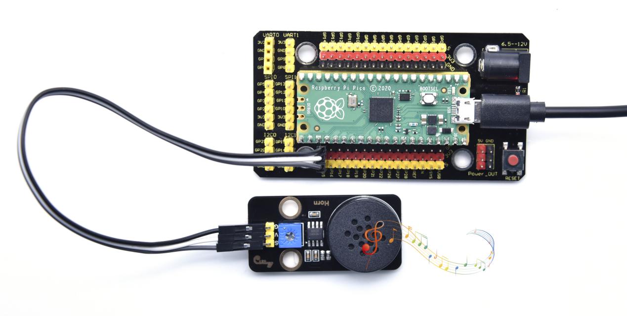
Project 49: Extinguishing Robot

Description
Today we will use Arduino simulation to build an extinguishing robot that will automatically sense the fire and start the fan. In this project we will learn how to build a very simple robot using pico, (detecting flames with a flame sensor, blowing out candles with a fan) can teach us basic concepts about robotics. Once you understand the basics below, you can build more complex robots.
Components Required
|
|
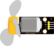 |
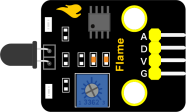 |
|
|
| Raspberry Pi Pico Board*1 | Raspberry Pi Pico Expansion Board*1 | 130 Motor*1 | Flame Sensor*1 | 4P Dupont Wire*2 | Micro USB Cable*1 |
Connection Diagram
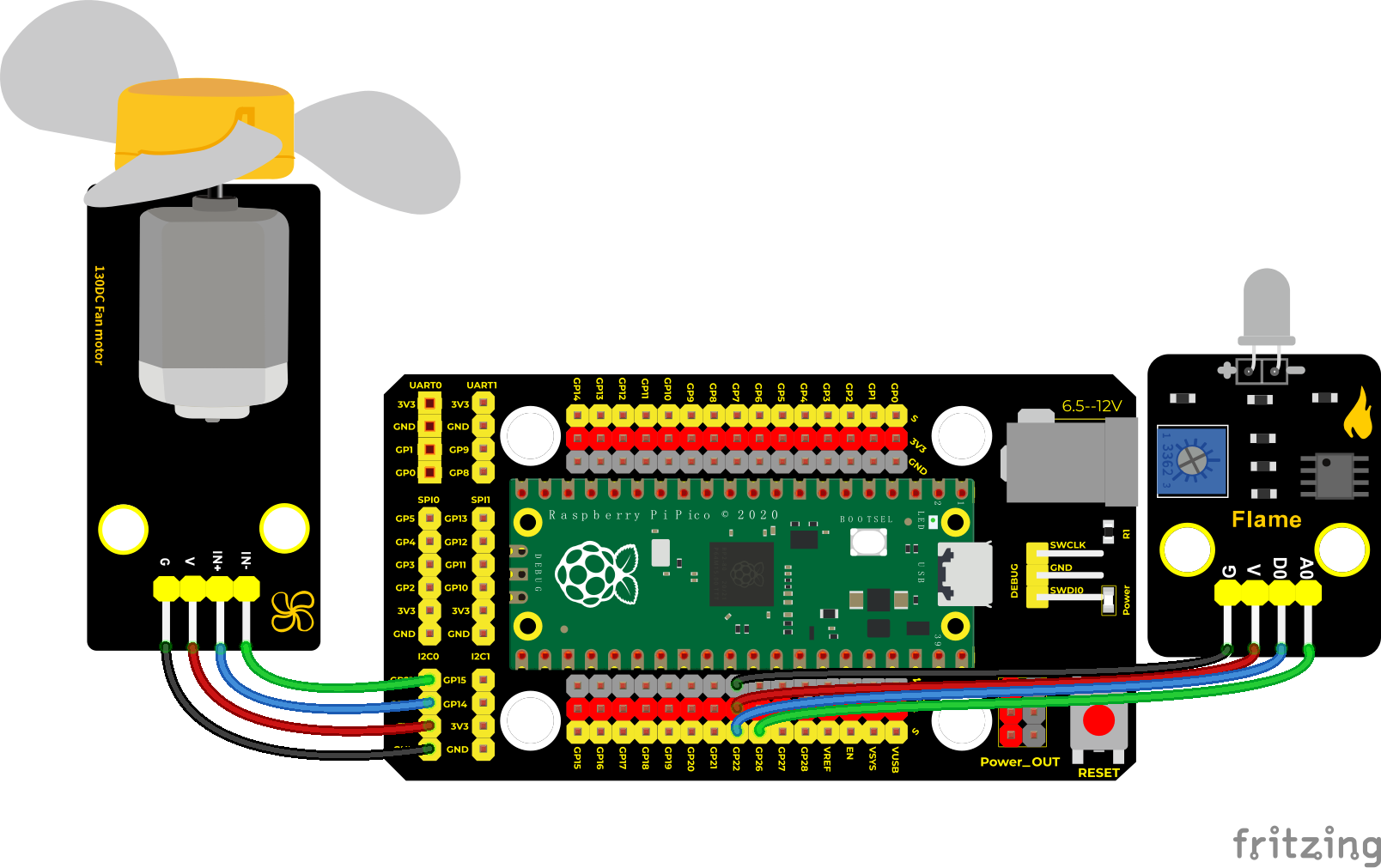
Test Code
/*
Keyestudio 42 in 1 Starter Kit for Raspberry Pi Pico
lesson 49
Self-extinguishing
http://www.keyestudio.com
*/
int item = 0;
**void setup() **
**void loop() else **
delay(100);
}
Code Explanation
In the code, we set the threshold value to 2000. When the flame sensor detects that the analog value is lower than this threshold, the fan will automatically turn on; otherwise, it will be turned off. For the driving method of the fan, please refer to the previous experiment sixteen 130 motor.
Test Result
Wire up and upload the test code, power up, open the monitor and set baud rate to 9600. When this value is less than 2000, the fan will works to blow out the fire. Basically, the flame value can be set by yourself.
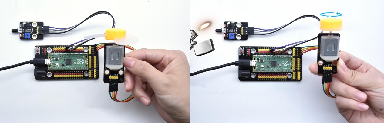
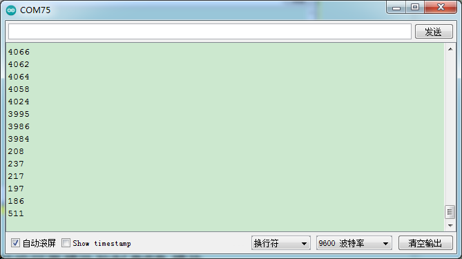
Project 50: Rotary Encoder
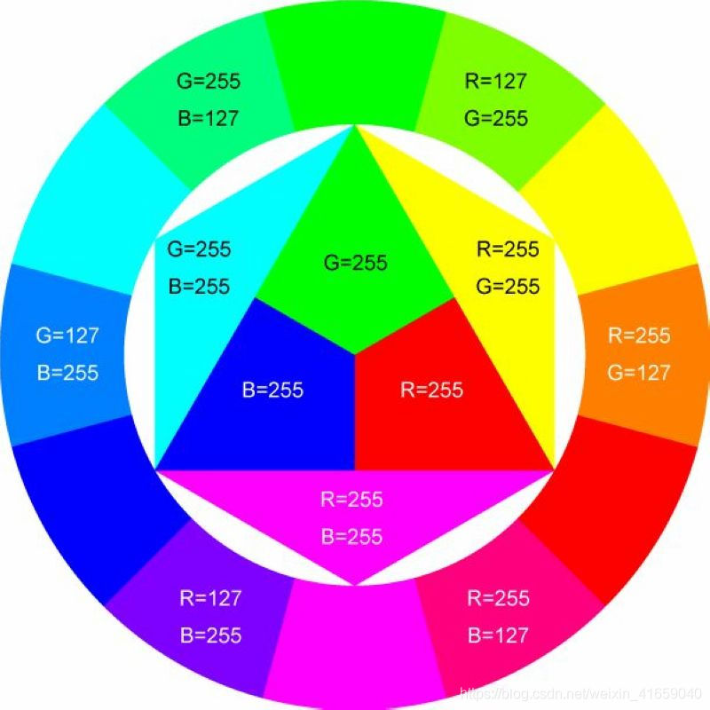
Introduction
In this lesson, we will control the LED on the RGB module to show different colors through a rotary encoder.
When designing the code, we need to divide the obtained values by 3 to get the remainders. The remainder is 0 and the LED will become red. The remainder is 1, the LED will become green. The remainder is 2, the LED will turn blue.
Components
|
|
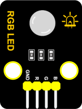 |
|
| Raspberry Pi Pico Board*1 | Raspberry Pi Pico Shield*1 | Keyestudio Common Cathode RGB Module*1 | Keyestudio Rotary Encoder Module*1 |
|
|
|
|
| 5P Dupont Wire*1 | 4P Dupont Wire*1 | Micro USB Cable*1 |
Connection Diagram
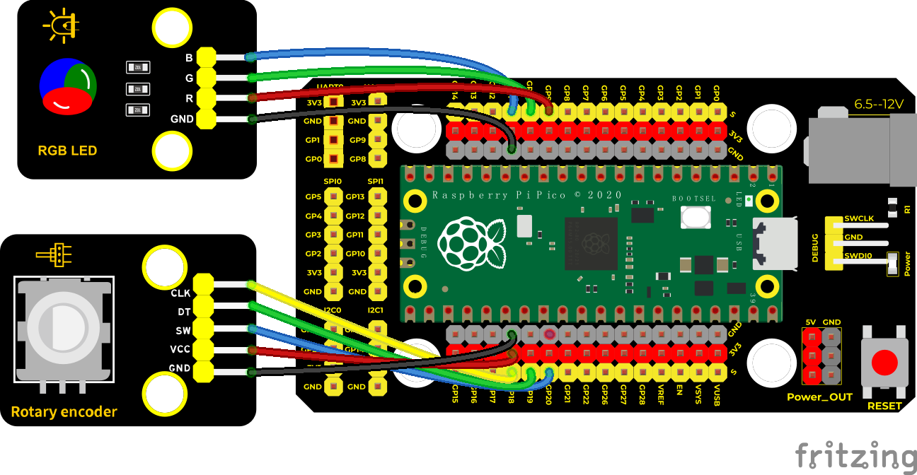
Test Code
/*
Keyestudio 42 in 1 Starter Kit for Raspberry Pi Pico
lesson 50
Encoder control RGB
http://www.keyestudio.com
*/
//Interfacing Rotary Encoder with Arduino
//Encoder Switch -> pin 20
//Encoder DT -> pin 19
//Encoder CLK -> pin 18
int Encoder_DT = 19;
int Encoder_CLK = 18;
int Encoder_Switch = 20;
int Previous_Output;
int Encoder_Count;
int redPin = 9; //connect the red LED D9
int greenPin = 10; //connect the green LED to D10
int bluePin = 11; //connect the blue LED to D11
int val;
**void setup() **
**void loop() **
else
}
Previous_Output = digitalRead(Encoder_DT);
if (digitalRead(Encoder_Switch) == 0)
}
**if (val == 0) else if (val == 1) else **
}
Code Explanation
In the experiment we set val to the remainder of dividing Encoder_Count by 3. Encoder_Count is the value of the encoder. After getting the remainder, set the pins to 9 (red light), 10 (green light) and 11 (blue light) according to the wiring.
2. Referring to the control method learned in the previous experiment, use the LED on the remainder control module to display the corresponding light color. The value obtained by taking the remainder of 3 for any number is 0 or 1 or 2. We use these three values to judge, and Display the corresponding color.
Test Result
Wire up, run the code, open the serial monitor and set baud rate to 9600. Rotate the knob of the rotary encoder to display the reminders, which can control colors of LED.
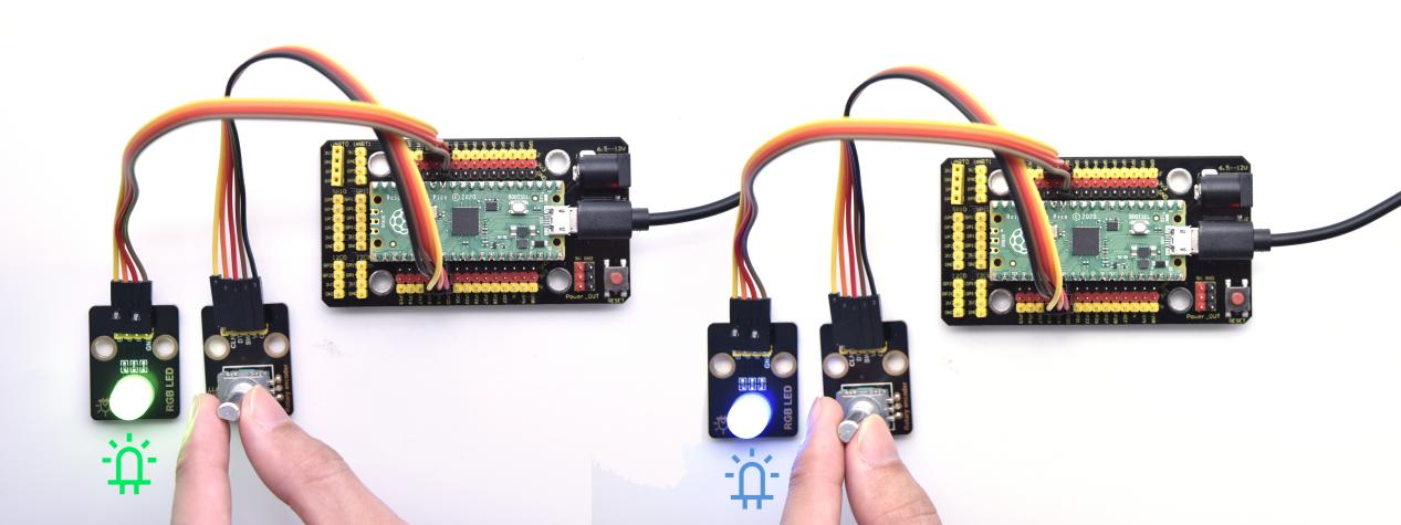
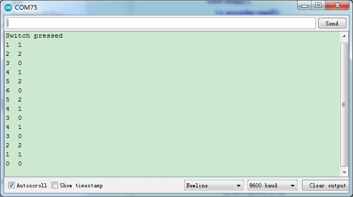
Project 51: Rotary Potentiometer

Introduction
In the previous courses, we did experiments of breathing light and controlling LED with button. In this course, we do these two experiments by controlling the brightness of LED through an adjustable potentiometer. The brightness of LED is controlled by PWM values, and the range of analog values is the same as the PWM’s, from 0 to 65535.
After the code is set successfully, we can control the brightness of the LED on the module by rotating the potentiometer.
Components
|
|
|
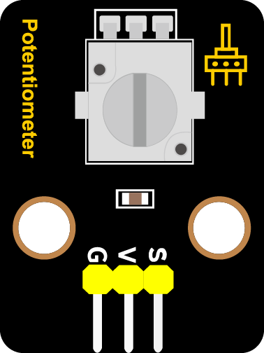 |
|
|
| Raspberry Pi Pico Board*1 | Raspberry Pi Pico Shield*1 | Keyestudio White LED Module*1 | Keyestudio Rotary Potentiometer*1 | 3P Dupont Wire*2 | MicroUSB Cable*1 |
Connection Diagram
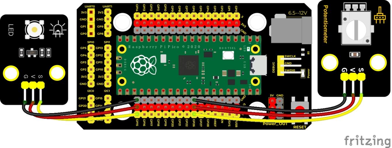
Test Code
/*
Keyestudio 42 in 1 Starter Kit for Raspberry Pi Pico
lesson 51
adjust the light
http://www.keyestudio.com
*/
int val1 = 0;//used to save analog values
int val2 = 0;//used to save the PWM value to be output
**void setup() **
**void loop() **
Code Explanation
In the experiment, the mapping function maps val1 from the range of 0-4095 to 0-255, and assigns it to val2.
Test Result
Run the test code and turn the potentiometer on the module to adjust the brightness of the LED on the LED module.
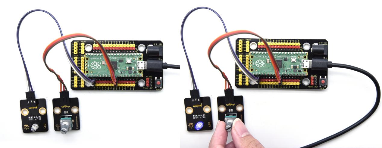
Project 52: Smart Windows

Description
In life, we can see all kinds of smart products, such as smart home. Smart homes include smart curtains, smart windows, smart TVs, smart lights, and more. In this experiment, we use a steam sensor to detect rainwater, and then achieve the effect of closing and opening the window by a servo.
Required Components
|
|
|
|
|
|
| Raspberry Pi Pico Board*1 | Raspberry Pi Pico Expansion Board*1 | Keyestudio Steam Sensor*1 | Servo*1 | 3P Dupont Wire*1 | Micro USB Cable*1 |
Wiring Diagram
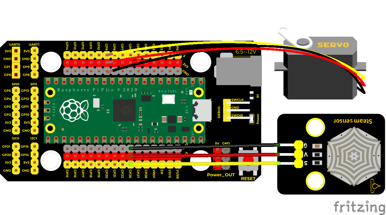
Test Code
/*
* Keyestudio 42 in 1 Starter Kit for Raspberry Pi Pico
* lesson 52
* smart window
* http://www.keyestudio.com
*/
#include <Servo.h>//import the library of the servo
int item = 0;//save the variable of the steam sensor
Servo myservo;//Define an instance of the servo example
void setup()
**void loop() else **
}
Code Explanation
We can control a servo to rotate by a threshold
Test Result
Wire up and run the test code. When the sensor detects a certain amount of water, the servo rotates to achieve the effect of closing or opening windows.
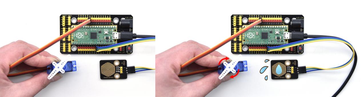
Project 53: Sound Activated Light
Introduction
In this lesson, we will make a smart sound activated light using a sound sensor and an LED module. When we make a sound, the light will automatically turn on; when there is no sound, the lights will automatically turn off. How it works? Because the sound-controlled light is equipped with a sound sensor, and this sensor converts the intensity of external sound into a corresponding value. Then set a threshold, when the threshold is exceeded, the light will turn on, and when it is not exceeded, the light will go out.
Components
|
|
 |
|
|
|
| Raspberry Pi Pico Board*1 | Raspberry Pi Pico Shield*1 | Keyestudio Sound Sensor*1 | Keyestudio White LED Module*1 | 3P Dupont Wire*2 | MicroUSB Cable*1 |
Connection Diagram
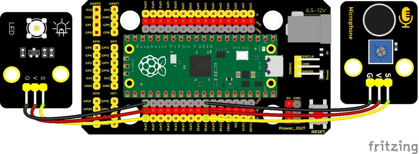
Test Code/*
Keyestudio 42 in 1 Starter Kit for Raspberry Pi Pico
lesson 53
sound-controlled lights
http://www.keyestudio.com
*/
int ledPin = 15;//LED is connected to GP15
int microPin = 26;//the sound sensor is connected to ADC0 (GP26)
**void setup() **
void loop() else
delay(100);
}
Code Explanation
We set the analog threshold value to 200. If more than 200, LED will be on 3s; on the contrary, it will be off.
Test Result
Run the test code, the monitor displays the corresponding volume value. When the analog value of sound is greater than 200, the LED on the LED module will light up, otherwise it will go off.
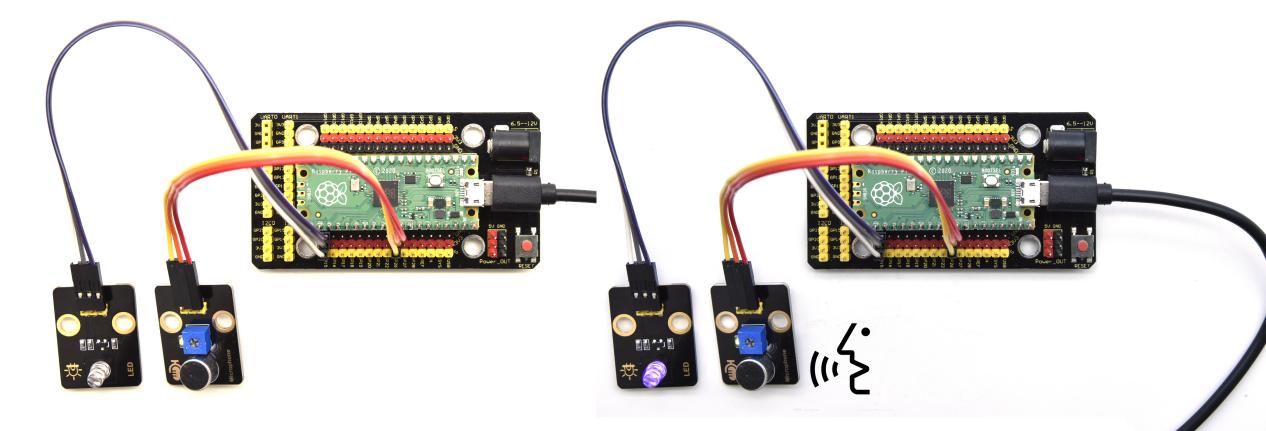
Project 54: Fire Alarm

Description
In this experiment, we will make a fire alarm system. Just use a flame sensor to control an active buzzer to emit sounds.
Required Components
|
|
|
|
| Raspberry Pi Pico Board*1 | Raspberry Pi Pico Expansion Board*1 | Keyestudio DIY电Active Buzzer*1 | keyestudio DIY Flame Sensor*1 |
|
|
|
|
| Micro USB Cable*1 | 3P Dupont Wire*1 | 4P Dupont Wire*1 |
Wiring Diagram
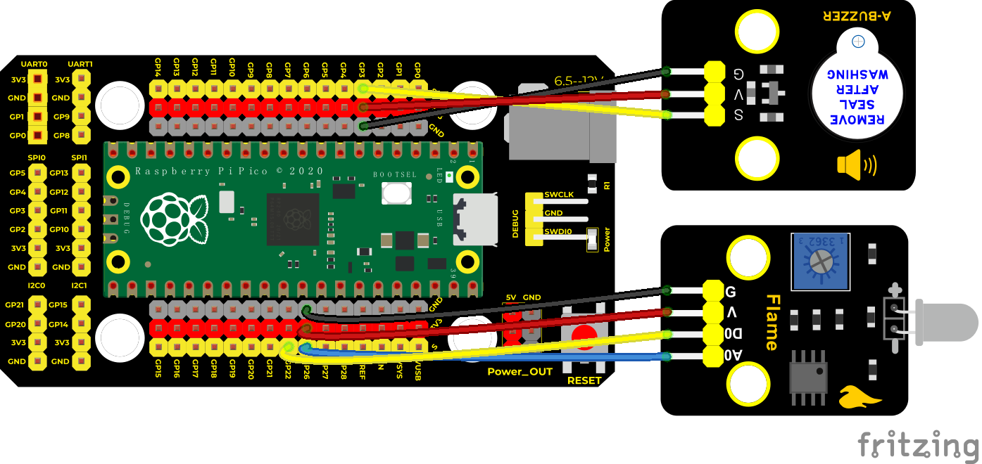
Test Code
/*
* Keyestudio 42 in 1 Starter Kit for Raspberry Pi Pico
* lesson 54
* flame alarm
* http://www.keyestudio.com
*/
int item = 0;
**void setup() **
**void loop() else **
delay(100);//delay in 100ms
}
Code Explanation
This flame sensor uses an analog pin and a digital pin. When a flame is detected, the digital pin outputs a low level. In this experiment we will use the digital port.
Test Result
Wire up, run the test code and power on. The sensor detects the flame, and the external active buzzer will emit sounds, otherwise the active buzzer will not emit sounds.
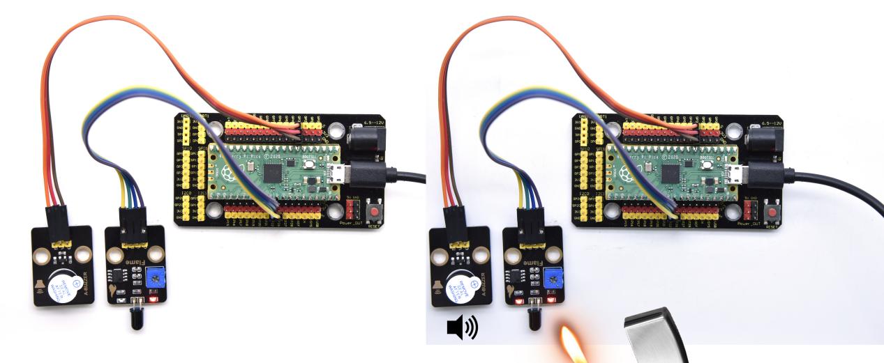
Project 55: Smoke Alarm

Description
In this experiment, we will make a smoke alarm by a TM16504-Digit segment module, a gas sensor and an active buzzer.
Required Components
|
|
|
|
| Raspberry Pi Pico Board*1 | Raspberry Pi Pico Expansion Board*1 | Keyestudio Active Buzzer*1 | Keyestudio TM16504-Digit Segment Module*1 |
|
|
|
|
| keyestudio Analog Gas Senso*1 | 3P Dupont Wire*1 | 4P Dupont Wire*2 | Micro USB Cable*1 |
Wiring Diagram
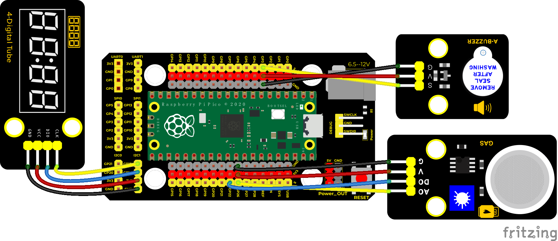
Test Code
/*
* Keyestudio 42 in 1 Starter Kit for Raspberry Pi Pico
* lesson 55
* smoke alarm
* http://www.keyestudio.com
*/
#include “KETM1650.h” //import the library of TM1650
int val = 0; //display values
//two ports are GP14 and GP15
#define DIO 14
#define CLK 15
KETM1650 tm_4display(CLK, DIO);
**void setup() **
**void loop() else **
delay(100);//delay in 100ms
}
Code Explanation
Define an integer variable val to store the analog value of the smoke sensor, and then we display the analog value in the four-digit digital tube, and then set a threshold, and when the threshold is reached, the buzzer will sound.
Test Result
Run the test code, wire up and power on. When the concentration of combustible gas exceeds the standard, the active buzzer module will give an alarm, and the four-digit digital tube will display the concentration value.
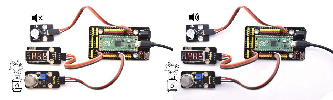
Project 56: Alcohol Sensor

Description
In the last experiment, we made a smoke alarm. In this experiment, we combine the active buzzer, the MQ-3 alcohol sensor, and a four-digit digital tube to test the alcohol concentration through the alcohol sensor. Then, the concentration to control the active buzzer alarm and the four-digit digital tube to display the concentration. So as to achieve the simulation effect of alcohol detector.
Components Required
|
|
|
|
| Raspberry Pi Pico Board*1 | Raspberry Pi Pico Expansion Board*1 | Active Buzzer | Keyestudio TM1650 4-Digit Module*1 |
|
|
|
|
| keyestudio Alcohol Sensor*1 | 3P Dupont Wire*1 | 4P Dupont Wire*2 | Micro USB Cable*1 |
Connection Diagram
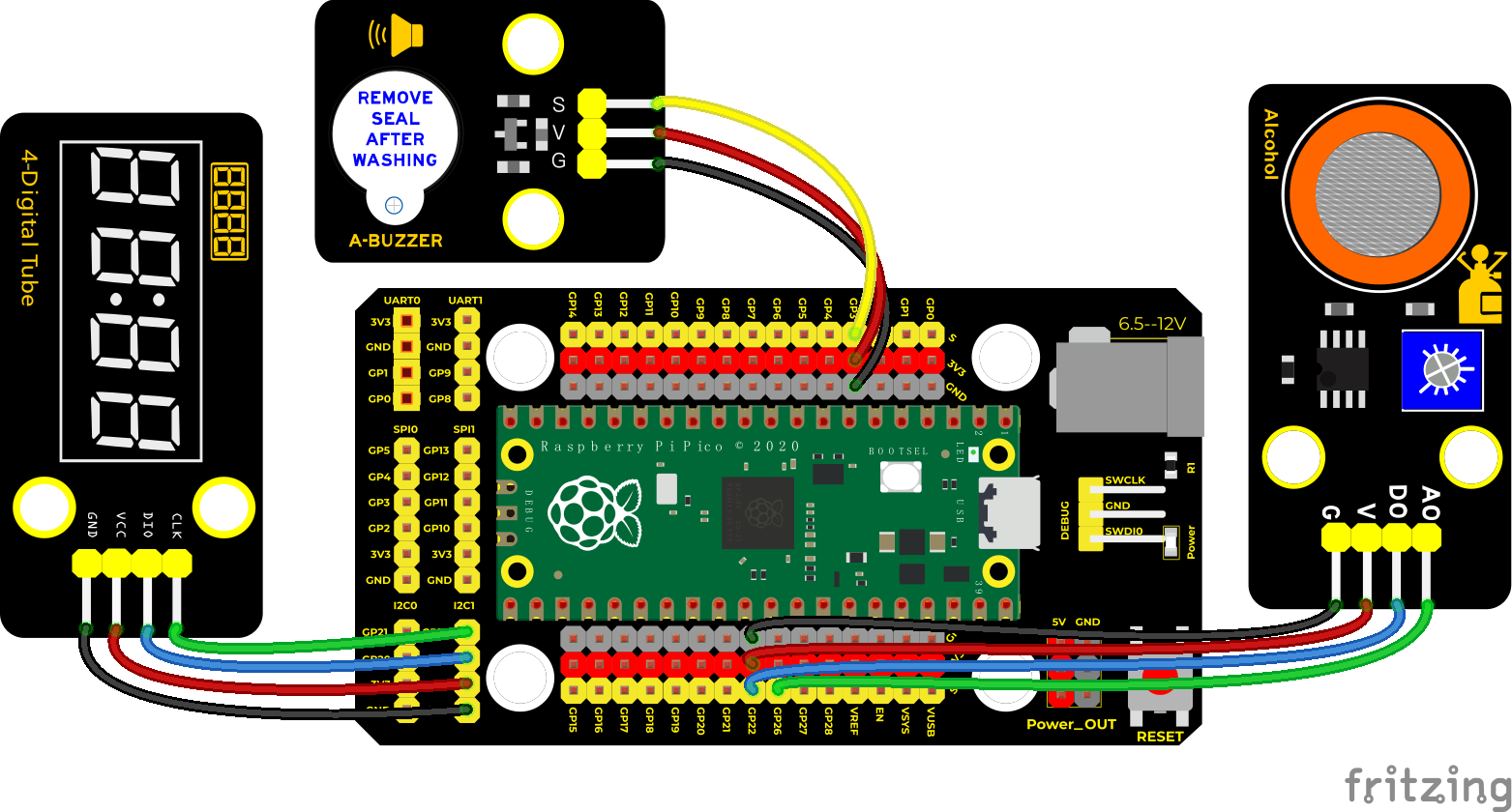
Test Code
/*
* Keyestudio 42 in 1 Starter Kit for Raspberry Pi Pico
* lesson 56
* breathalyzer
* http://www.keyestudio.com
*/
#include “KETM1650.h” //Import the library file of TM1650
int val = 0; //display values
//ports are connected to GP14, GP15
#define DIO 14
#define CLK 15
KETM1650 tm_4display(CLK, DIO);
**void setup() **
**void loop() else **
delay(100);//delay in 100ms
}
Code Explanation
The code setting is the same as the previous experiment, define an integer variable val to store the analog value of the alcohol sensor, and then we display the analog value in the four-digit digital tube, and then set a threshold, when the threshold is reached, the predestined buzzer sounded.
Test Result
Wire up according to the wiring diagram and run the test code. When different alcohol concentrations are detected, the active buzzer module will alarm, and the four-digit digital display will show the concentration value.
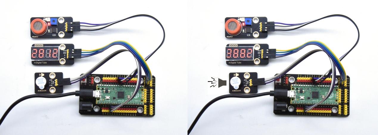
Project 57: 6812 RGB Module

Description
We learned how to use the 6812 RGB module, we knew that this module can light up each LED through a pin. In this experiment, we will control the RGB module to display different colors. (Note: do not look directly at the LEDs for a long time to avoid damage to our eyes.)
Components
|
|
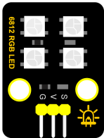 |
|
|
| Raspberry Pi Pico Board*1 | Raspberry Pi Pico Shield*1 | Keyestudio 6812 RGB Module*1 | 3P Dupont Wire*1 | MicroUSB Cable*1 |
Connection Diagram

Test Code
/*
Keyestudio 42 in 1 Starter Kit for Raspberry Pi Pico
lesson 57
SK6812 RGB
http://www.keyestudio.com
*/
#include”rgb.h”
RGB rgb(15, 4); //rgb(pin, num); num = 0-100
//used to save the variable of RGB
int R = 0;
int G = 0;
int B = 0;
int num = 0;
**void setup() **
**void loop() **
rgb.setPixelColor(num, R, G, B); //set the color of num-1 light
rgb.show();//display
delay(100);//
}
Code Explanation
random(0, 255):Select a random integer between 0 and 255
.setPixelColor(num - 1, R, G, B):set the light beads at num-1 to display red, green and blue color
.show():display,if without this function , the function we set can’t work.
Test Result
Wire up the components and run the code. We will see LEDs on the 6812RGB module shows different colors.
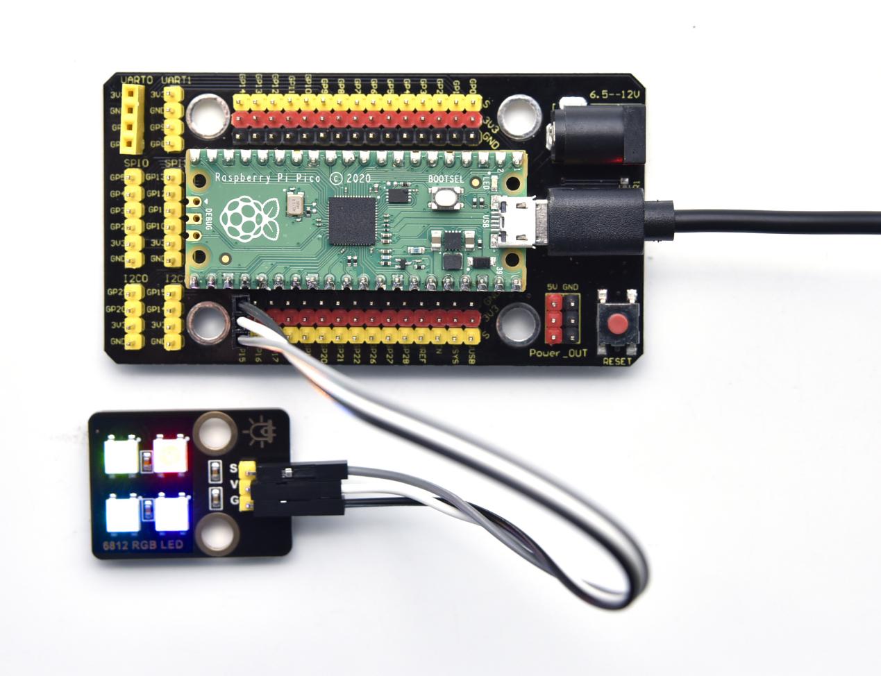
Project 58: Ultrasonic Radar
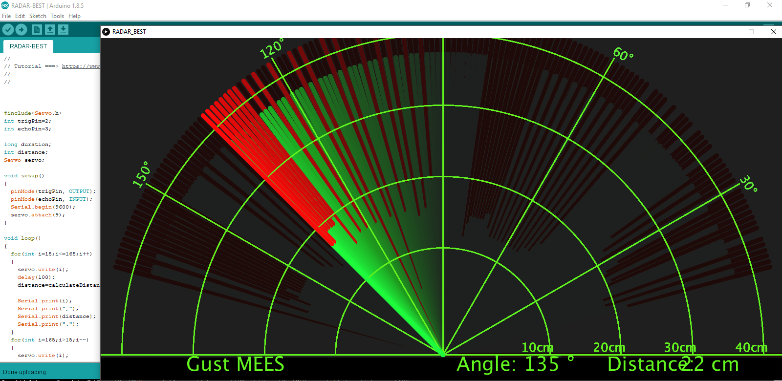
Description

We know that bats use echoes to determine the direction and the location of their preys. In real life, sonar is used to detect sounds in the water. Since the attenuation rate of electromagnetic waves in water is very high, it cannot be used to detect signals, however, the attenuation rate of sound waves in the water is much smaller, so sound waves are most commonly used underwater for observation and measurement.In this experiment, we will use a speaker module, an RGB module and a 4-digit tube display to make a device for detection through ultrasonic.

Components
|
|
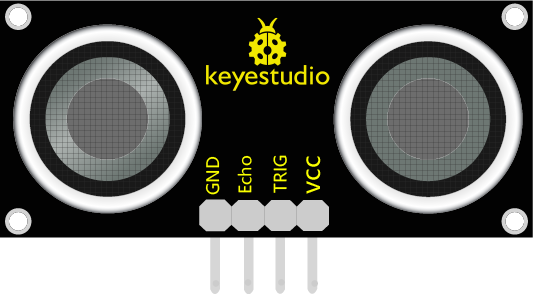 |
|
|
| Raspberry Pi Pico Board*1 | Raspberry Pi Pico Shield*1 | keyes brick HC-SR04 Ultrasonic Sensor*1 | Keyestudio Speaker Module*1 | Keyestudio Common Cathode RGB Module*1 |
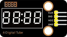 |
|
|
|
|
| Keyestudio TM1650 4-Digit Tube Display*1 | 4P Dupont Wire*3 | 3P Dupont Wire*1 | MicroUSB Cable*1 |
Wiring Diagram
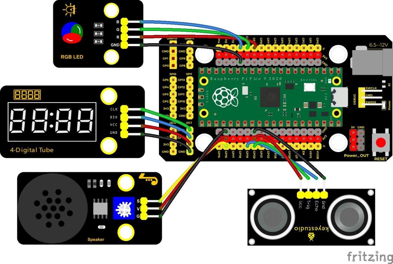
Test Code
/*
Keyestudio 42 in 1 Starter Kit for Raspberry Pi Pico
lesson 58
Ultrasonic radar
http://www.keyestudio.com
*/
#include “KETM1650.h”//the library file of the 4-digit tube display
KETM1650 tm_4display(15, 14);
int beeppin = 16; //define GP16
int EchoPin = 19; //Echo is connected to GP19
int TrigPin = 20; //Trig is connected to GP20
int distance;//distance detected by the ultrasonic sensor
int redPin = 9; //make the red LED connect to GP9
int greenPin = 10; //make the green LED connect to GP10
int bluePin = 11; //make the blue LED connect to GP11
**float checkdistance() **
**void setup() **
**void loop() else if (distance > 10 && distance <= 20) else **
}
Code Explanation
We set sound frequency and light color by adjusting different distance range.
We can adjust the distance range in the code.
Test Result
Wire up according to the connection diagram upload the run the code and power up. When the ultrasonic sensor detects different distances, the buzzer will produce different frequencies of sound, the RGB will show different colors, and the measured distances are displayed on the 4-digit tube display.
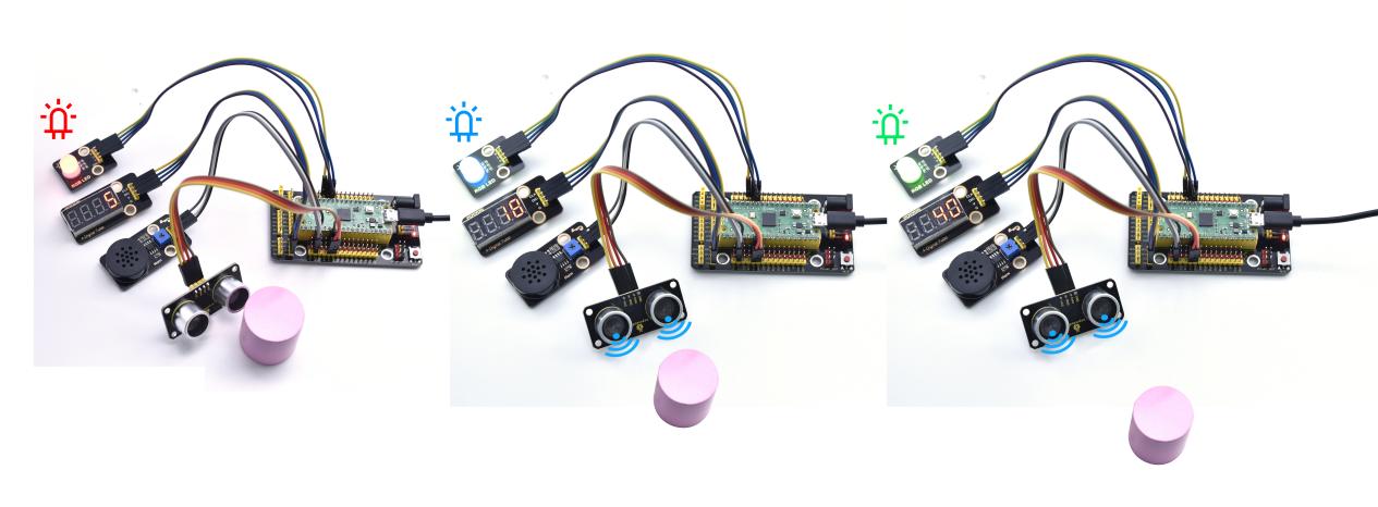
Project 59: IR Remote Control
Introduction
In the previous experiments, we learned to turn on or turn off the LED, adjust the brightness of a light through PWM, and how to use the infrared receiver module. So in this experiment, we use an infrared remote control to control an LED module.
When we receive a value, we set the PWM value by the corresponding button value, thus you can adjust the brightness. Control the LED to turn on or turn off is in the same way. If we want to use the same button to control the LED to turn on or turn off, we can achieve it through the code.
Components
|
|
|
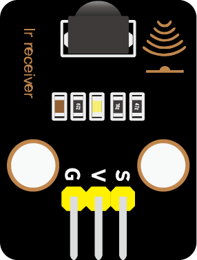 |
| Raspberry Pi Pico Board*1 | Raspberry Pi Pico Shield*1 |
Keyestudio White LED Module*1 | Keyestudio IR Receiver*1 |
|
|
|
|
| MicroUSB Cable*1 | Remote Control*1 | 3P Dupont Wire*2 |
Connection Diagram
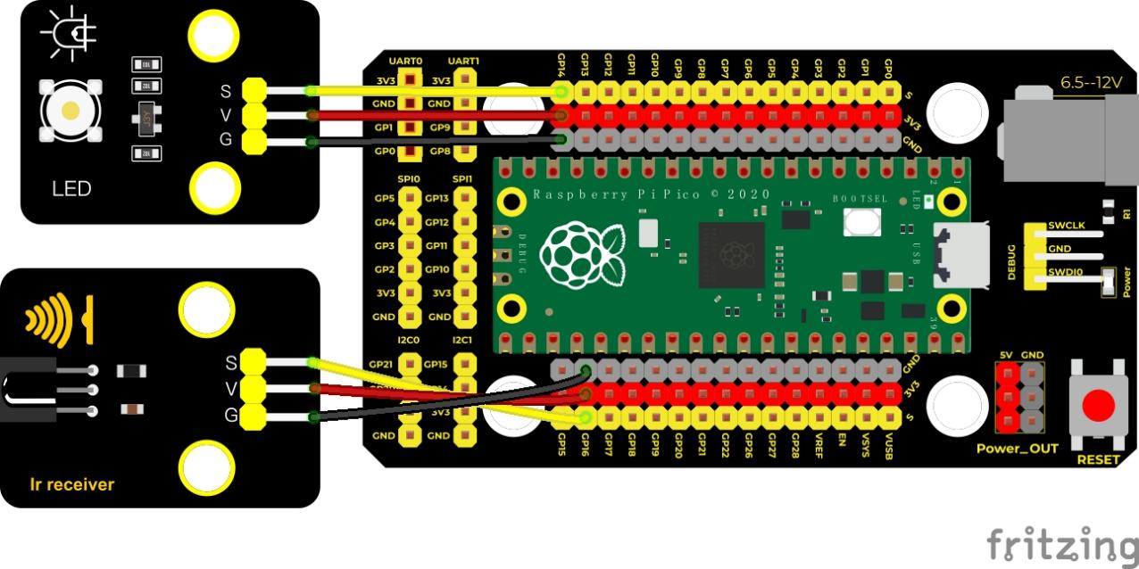
Test Code
/*
Keyestudio 42 in 1 Starter Kit for Raspberry Pi Pico
lesson 59
IR control LED
http://www.keyestudio.com
*/
#include”ir.h”
IR IRreceive(16);//IR receiver is connected to GP16
int led = 14;//LED is connected to GP14
boolean flag = true;//LED flag bit
**void setup() **
////////////////////
**void loop() else **
}
}
}
}
Code Explanation
We define a boolean variable. There are two boolean variables. true (true) or false (false), boolean flag = true.
2. When we press the OK button, the value of infrared reception is 64. At this time, we need to set a boolean variable flag. When the flag is true (true), the LED is turned on, and when it is false (false), the LED is turned off and turned on. After the LED is on and set it to false. We press the OK key, the LED will be off.
Test Result
Wire up, upload the test code, open the serial monitor and set baud rate to 9600. Press the OK button of the remote, the LED will be on; press it again, the LED will be off.
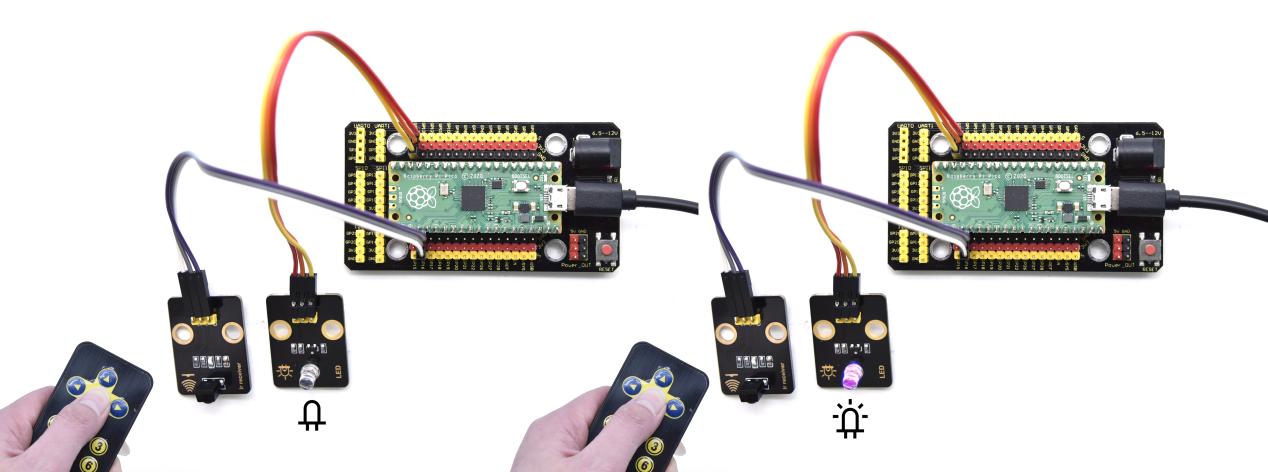
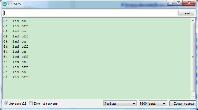
Project 60: Heat Dissipation Device

Description
We will use a temperature sensor and some modules to make a smart cooling device in this experiment. When the ambient temperature is higher than a certain value, the motor is turned on, thereby reducing the ambient temperature and achieving the heat dissipation effect. Then display the temperature value in the four-digit segment display.
Required Components
|
|
|
|
| Raspberry Pi Pico Board*1 | Raspberry Pi Pico Expansion Board*1 | keyestudio 130 Motor*1 | Keyestudio TM1650 4-Digit Segment Display*1 |
|
|
|
|
| Keyestudio 18B20 Temperature Sensor*1 | 3P Dupont Wire*1 | 4P Dupont Wire*2 | Micro USB Cable*1 |
Wiring Diagram
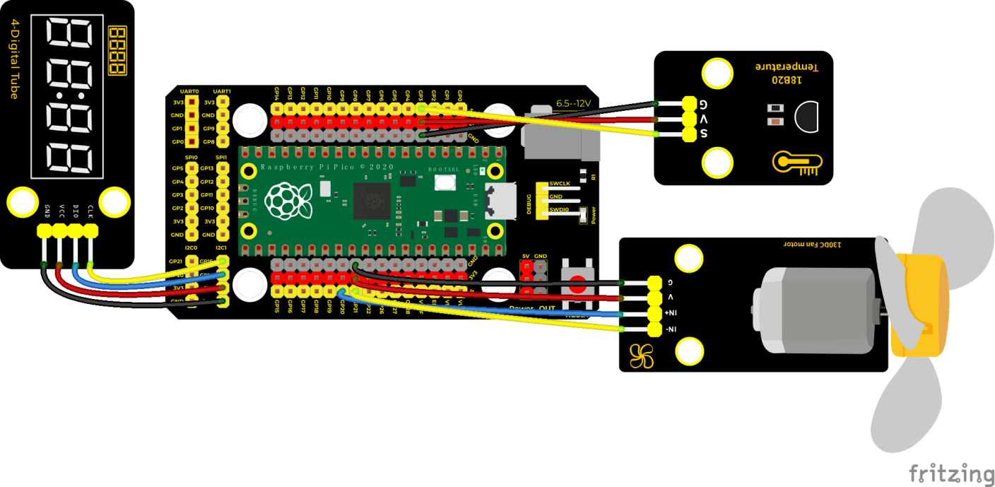
Test Code
/*
* Keyestudio 42 in 1 Starter Kit for Raspberry Pi Pico
* lesson 60
* heat abstractor
* http://www.keyestudio.com
*/
#include <DS18B20.h>
#include “KETM1650.h” //import the library of TM1650
//two ports are GP14 and GP15
#define DIO 14
#define CLK 15
KETM1650 tm_4display(CLK, DIO);
//ds18b20 pin to 3
DS18B20 ds18b20(3);
**void setup() **
**void loop() else **
delay(100);
}
Code Explanation
The setting of variables and the storage of detection values are the same as what we learned earlier. We also set a temperature threshold and control the rotation of the motor when the threshold is exceeded, and then we use the digital tube to display the temperature value.
Test Result
Wire up and run the test code. We can see the temperature of the current environment (unit is Celsius) on the four-digit segment display, as shown in the figure below. If this value exceeds the value we set, the fan will rotate to dissipate heat.
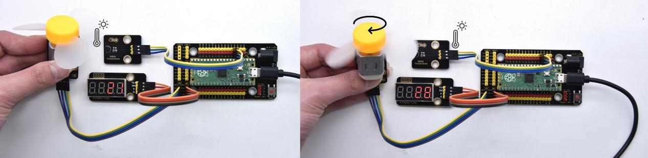
Project 61: Intelligent Entrance Guard System

Description
In this project, we use the RFID522 card swiping module and the servo to set up an intelligent access control system. The principle is very simple.We use RFID522 swipe card module, an IC card or key card to unlock
Required Components
|
|
|
|
| Raspberry Pi Pico Board*1 | Raspberry Pi Pico Expansion Board*1 | Key*1 | IC Card*1 |
|
|
|
|
| Keyestudio RFID Module*1 | Servo*1 | 4P Dupont Wire*1 | Micro USB Cable*1 |
Wiring Diagram
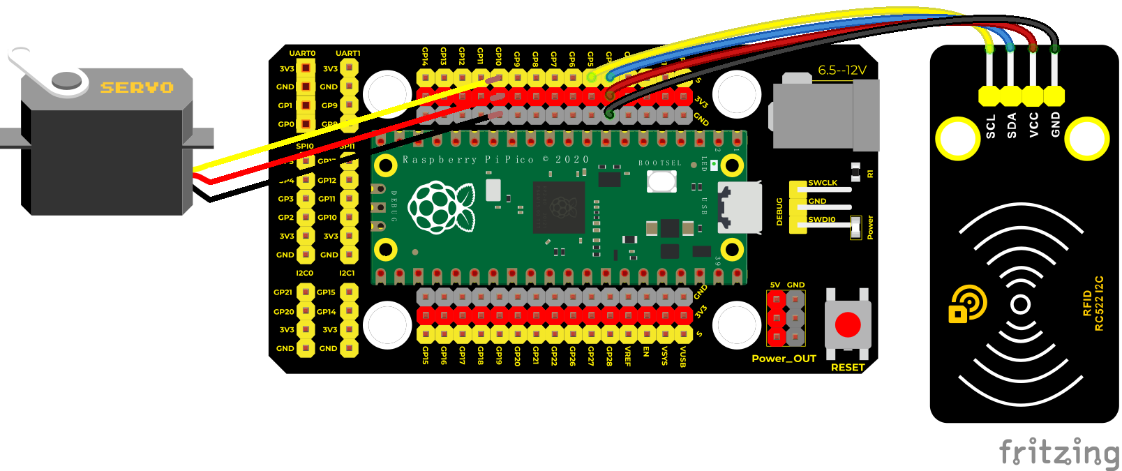
Test Code
/*
* Keyestudio 42 in 1 Starter Kit for Raspberry Pi Pico
* lesson 61
* Intelligent access control
* http://www.keyestudio.com
*/
#include <Servo.h>
#include <Wire.h>
#include <MFRC522_I2C.h>
MFRC522 mfrc522(0x28);
Servo myservo;
String rfid_str = “”;
**void setup() **
**void loop() **
rfid_str = “”;//character strings clear up
Serial.print(F(“Card UID:”));
**for (byte i = 0; i < mfrc522.uid.size; i++) **
Serial.println(rfid_str);
**if (rfid_str == “8dfe6c4d” || rfid_str == “bc33766e”) **
}
Code Explanation
In the previous experiment, our card swipe module has tested the information of IC card and key. Then we use this corresponding information to control the door.
Test Result
Upload the test code, wire up and power up with a USB cable, open the shell and set the baud rate to 9600; the shell displays information.
When we use the IC card or blue key to swipe the card, the shell displays the card information and “open the door”, as shown in the figure below, the servo rotates to the corresponding angle to simulate opening the door.
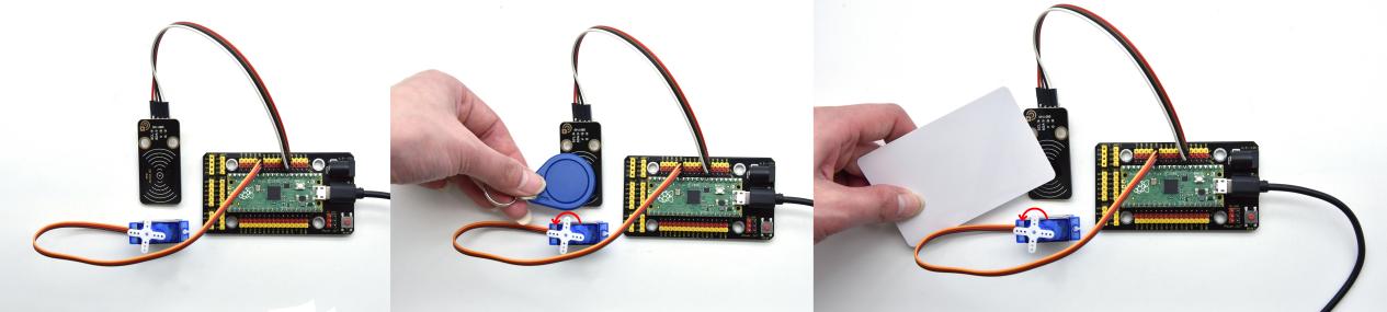
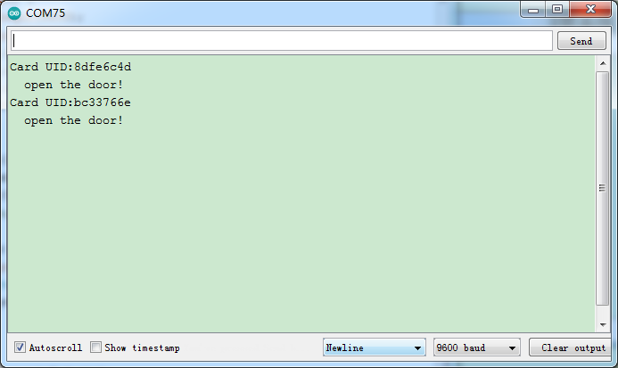
Project 62: Comprehensive Experiment

Introduction
We did a lot of experiments, and for each one we needed to re-upload the code, so can we achieve different functions through an experiment? In this experiment, we will use an external button module to achieve different functions.
|
|
|
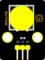 |
|
|
| Raspberry Pi Pico Board*1 | Raspberry Pi Pico Expansion Board*1 | Keyestudio DIY Purple LED Module*1 | Keyestudio Button Module*1 | Keyestudio Rotary Encoder*1 | Keyestudio Obstacle Avoidance Sensor*1 |
|
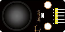 |
|
|
|
|
| Keyestudio IR Receiver*1 | Keyestudio DIY Joystick Module*1 | keyes brick HC-SR04 Ultrasonic sensor *1 | Keyestudio DIYCommon Cathode RGB Module *1 | Keyestudio XHT11 Temperature and Humidity Sensor *1 |
Keyestudio ADXL345 Acceleration Sensor*1 |
|
|
|
|
|
|
| Micro USB Cable*1 | 3PDupont Wire*6 | 4PDupont Wire*3 | 5PDupont Wire*1 | Remote Control*1 |
Components Required
Connection Diagram
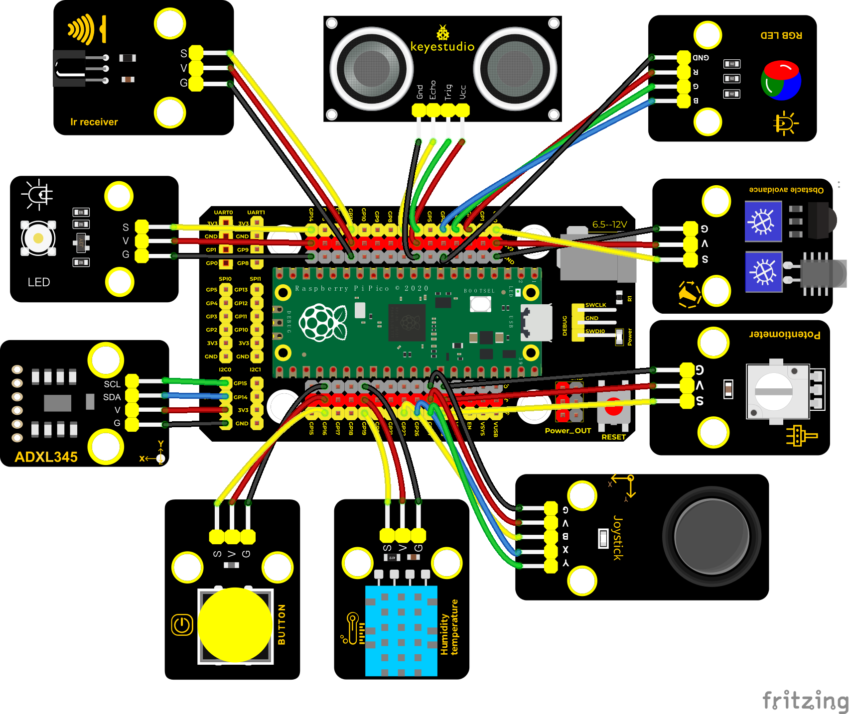
Test Code
/*
Keyestudio 42 in 1 Starter Kit for Raspberry Pi Pico
lesson 62
Comprehensive experiment
http://www.keyestudio.com
*/
#include”ir.h”//the library of IR receiver
#include “xht11.h”
#include “adxl345_io.h”
//ADXL345 sda–>20,scl–>21
adxl345 adxl345(20, 21);
//the IR receiver is connected to GP11
IR IRreceive(11);
//xht11 to gpio19
xht11 xht(19);
//rgb is connected to 2,3 and 4
int r_pin = 2;
int g_pin = 3;
int b_pin = 4;
//the joystick module is connected to ports
int X = 26;
int Y = 27;
int KEY = 22;
//The potentiometer pin is connected to the analog port 28
int resPin = 28;
//LED is connected to GP14
int LED = 14;
//the obstacle avoidance sensor is connected to GP0
int Avoid = 0;
//interfaces of the Ultrasonic sensor
int Trig = 6;
int Echo = 7;
//interfaces of the button module
int button = 16;
int PushCounter = 0;//save the number of pressing the button
int yushu = 0;
unsigned char dht[4] = ;//receive 32 bit data
bool ir_flag = 1;
float out_X, out_Y, out_Z;
**void counter() **
}
**void setup() **
**void loop() else if (yushu == 1) else if (yushu == 2) else if (yushu == 3) else if (yushu == 4) else if (yushu == 5) else if (yushu == 6) else if (yushu == 7) **
}
//RGB
**void yushu_0() **
//Infrared reception
**void yushu_1() **
}
}
**void yushu_2() else **
delay(1200);
}
**void yushu_3() **
**void yushu_4() **
**void yushu_5() **
**else **
delay(100);
}
**void yushu_6() **
**void yushu_7() **
**float checkdistance() **
Code Explanation
1. Calculate how many times the button is pressed, divide it by 8, and get the remainder which is 0, 1 2, 3, 4, 5 , 6 and 7. According to different remainders, construct five unique functions to control the experiment and realize different functions.
We add dht and adxl345 library files in this project.
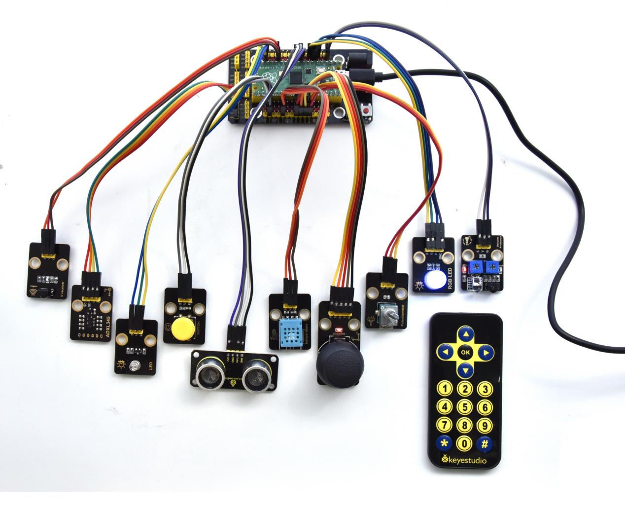
Test Result
Upload the test code, wire up and power on with a USB cable.
At the beginning, the number of the button is 0 and remainder is 0. Open the monitor and set baud rate to 9600. Press the button, the RGB stops flashing, press once, the remainder is 1. If we point at IR receiver with the infrared remote control and press the button,the serial monitor will display as follows.
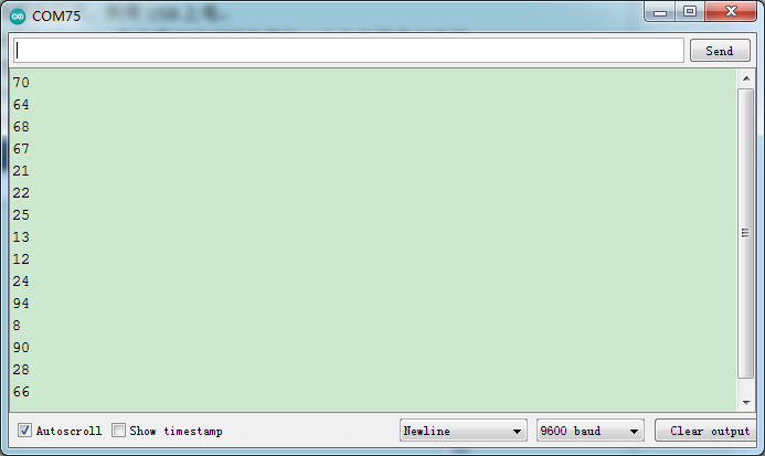
Press a key twice, the time of pressing buttons is 2 and the remainder is 2. Read temperature and humidity values. As shown below;
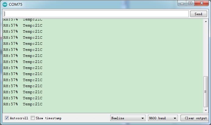
Press a key again, the time of pressing buttons is 3 and the remainder is 3. Read digital values at x, y and z axis of the joystick module. As shown below;
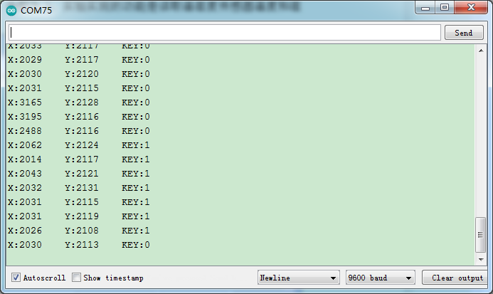
Press the key for the fourth time, the remainder is 4. Then the potentiometer can adjust the PWM value at the GP14 port to control LED brightness of the purple LED
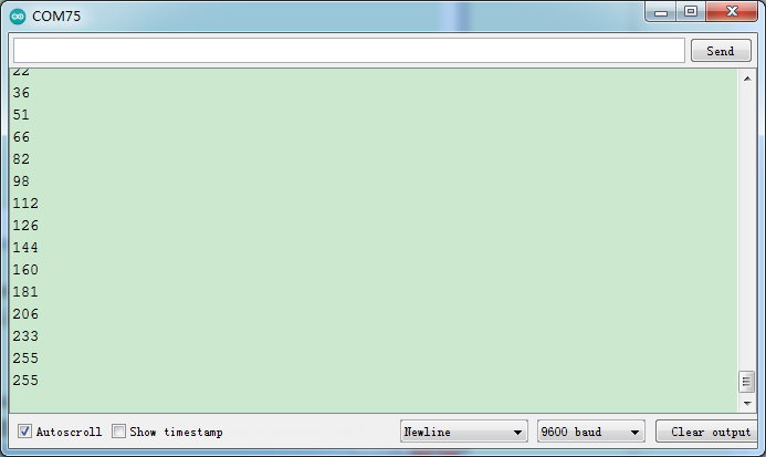
Press the key for the fifth time, the remainder is 5. Then the ultrasonic sensor can detect obstacles, as shown below;
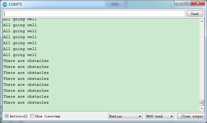
Press the key for sixth time and the remainder is 6. Then the distance away from the obstacle can be detected. As shown below;
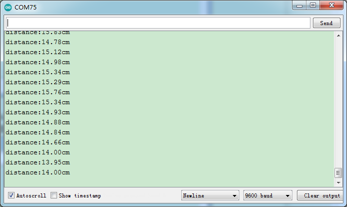
Press the key for seventh time and the remainder is 7. The shell will print out the acceleration values
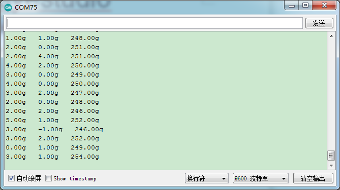
Press the key for eighth time and the remainder is 0. Then the RGB will flash. If you press keys incessantly, remainders will change in loop way. So does functions.